
Rotary cutting and clamping device for a processing machine

a processing machine and clamping technology, applied in the direction of manufacturing tools, saw chains, precision positioning equipment, etc., can solve the problems of wasting labor and time, processing a single work piece, and not being able to finish the processing

Inactive Publication Date: 2007-03-01
HER KWANG ENTERPRISE
View PDF7 Cites 5 Cited by
  • Summary
  • Abstract
  • Description
  • Claims
  • Application Information

AI Technical Summary

Benefits of technology

[0006] The objective of the invention is to offer a rotary cutting device and a clamping device for a processing machine, possible to adjust their cutting and clamping position for matching with the shape and the position of a work piece being processed and able to finish processing automatically and precisely with one round of operation.
[0012] 5. The power member of the power unit of the rotary cutting device is preferably a servomotor that is able to detect the condition of the rotary cutter and timely stop the rotary cutter from operating.

Problems solved by technology

However, when the rotary cutter is to be adjusted in position manually, the processing machine has to be stopped operating first, thus wasting much labor and time, and after processed, a batch of work pieces, which must be completely the same in shape, may be found different in quality.
However, such a device can only process a work piece in a single processing way, but cannot finish the processing by one-time operation for a work piece that needs to be processed in varied ways.

Method used


Image

  • Rotary cutting and clamping device for a processing machine
  • Rotary cutting and clamping device for a processing machine
  • Rotary cutting and clamping device for a processing machine

Examples


Embodiment Construction

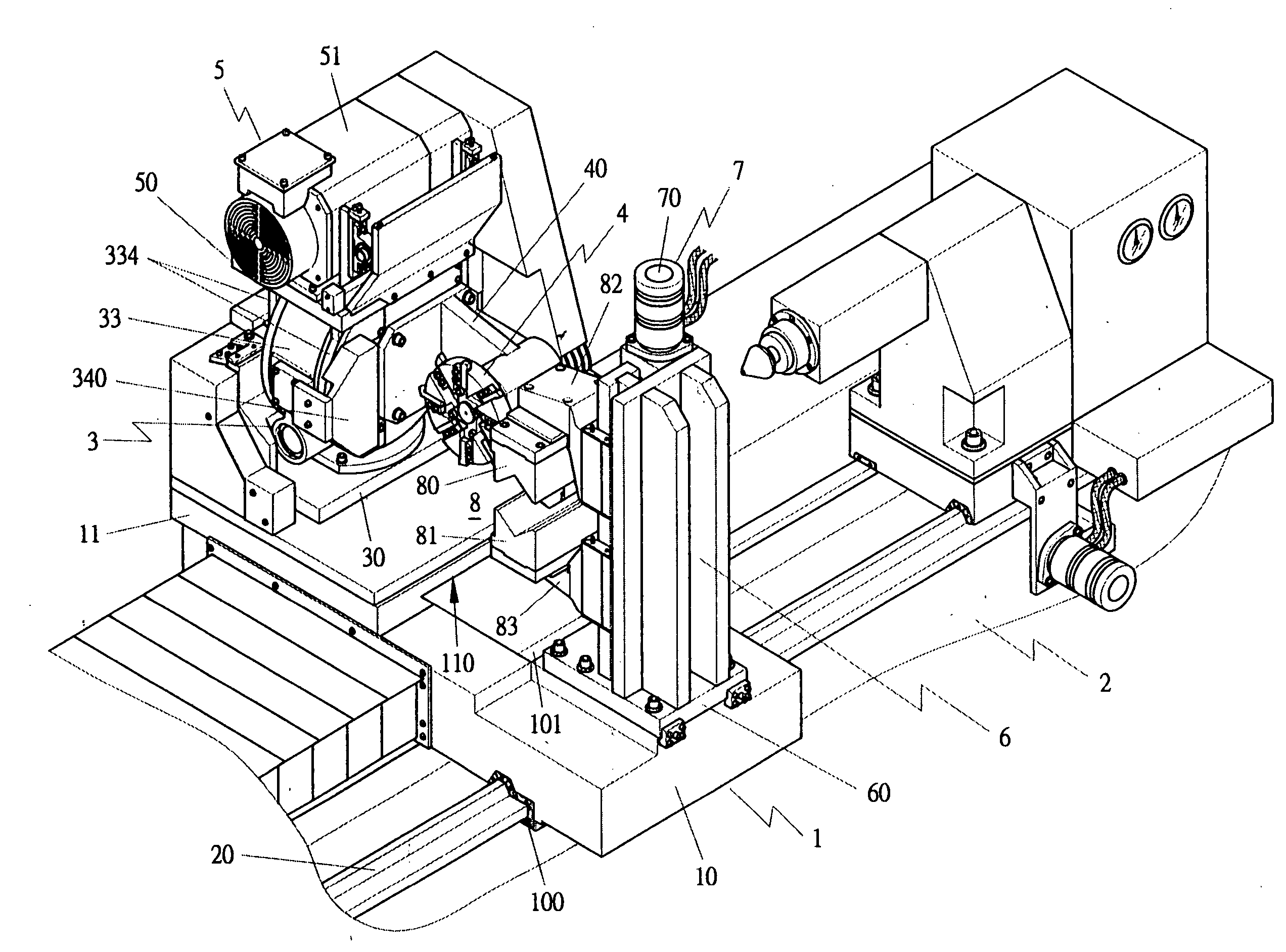
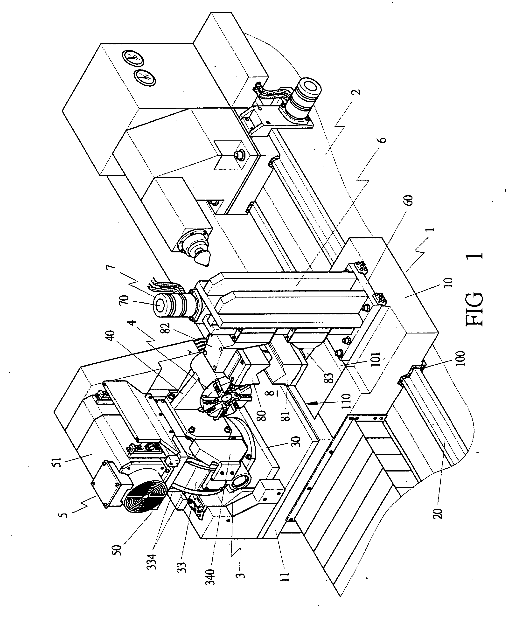
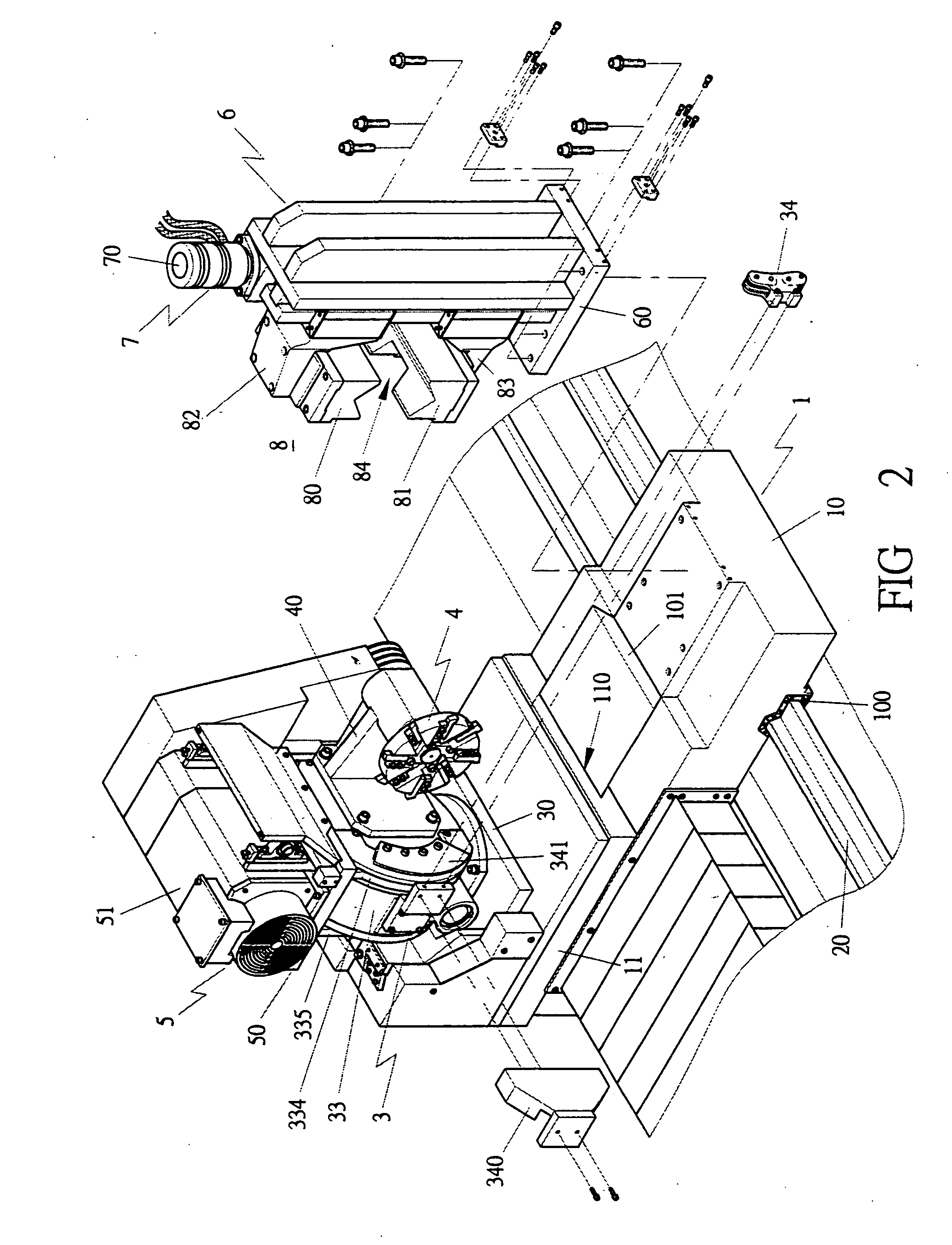
[0025] A preferred embodiment of a rotary cutting device for a processing machine in the present invention, as shown in FIGS. 1 to 4, includes a fundamental base 1, a rotary cutter holder 3 and a power unit 5 as main components.

[0026] The fundamental base 1 composed of a lower base 10 and an upper base 11. The lower base 10 is bored with a rail groove 100 to be combined with the rail 20 of a processing machine 2 to enable the fundamental base 1 to be moved left and right on the processing machine 2. The lower base 10 is further formed with a dovetail shaped rail 101. The upper base 11 is bored with a dovetail shaped groove 110 to be combined with the dovetail shaped rail 101 of the lower base 10 to enable the upper base 11 to be moved back and forth. Thus, the fundamental base 1 can be moved along definite tracks to match with the position of a work piece being processed.

[0027] The rotary cutter holder 3, as shown in FIGS. 3 and 4, is provided with a fixing base 30 and a height-ad...


PUM

PropertyMeasurementUnit
clamping distanceaaaaaaaaaa
sizeaaaaaaaaaa
shapeaaaaaaaaaa

Abstract

A rotary cutting device for a processing machine has a rotary cutter holder provided with an angle-adjusting device and a height-adjusting device. The angle-adjusting device is able to adjust the position of the rotary cutter of the rotary cutter base at any angle, and the height-adjusting device able to adjust the height of the rotary cutter base for matching with the shape and the position of a work piece A power unit is installed on the rotary cutter base for supplying the rotary cutter with power. A clamping device for a processing machine is provided with a clamping unit base having a clamping unit provided with an upper and a lower clamping member. The clamping unit base is provided with a power unit for adjusting the clamping distance between the two clamping members.

Description

BACKGROUND OF THE INVENTION [0001] 1. Field of the Invention [0002] This invention relates to a rotary cutting device and a clamping device for a processing machine, particularly to ones possible to be adjusted freely in their cutting and clamping position for matching with the shape and the position of a work piece, able to finish processing of the work piece automatically and precisely by only one-time operation, and economical in time and labor as well as cost. [0003] 2. Description the Prior Art [0004] Generally, to match with the shape and the position of a work piece being processed, the rotary cutter of a conventional metal processing machine has to be adjusted in position anytime. At present, position adjustment of the rotary cutter of a conventional processing machine is done by manual operation, and the processing height or angle of different work pieces has to be adjusted manually time after time. However, when the rotary cutter is to be adjusted in position manually, the...

Claims


Application Information

Patent Timeline
Patent Type & Authority Applications(United States)
IPC IPC(8): B26D1/00
CPCB23Q16/025Y10T83/929
Inventor LIN, CHUN-YIN
Owner HER KWANG ENTERPRISE
Learn More