Golf glove

a glove and golf technology, applied in the field of golf gloves, can solve the problems of difficulty in consistently hitting the golf ball with the club in an effective manner, and conventional gloves fail to enable the golfer to grip the club in the best manner

Inactive Publication Date: 2007-03-01
PARK KEY SOON
View PDF7 Cites 3 Cited by
  • Summary
  • Abstract
  • Description
  • Claims
  • Application Information

AI Technical Summary

Benefits of technology

[0007] It has been found that such a glove in accordance with the invention provides a golfer with better control of a club when hitting a ball.

Problems solved by technology

It is very well know that, even for professionals, it is difficult to consistently hit a golf ball with a club in an effective manner.
One reason may be that conventional gloves fail to enable a golfer to grip the club in the best manner possible.

Method used


Image

  • Golf glove
  • Golf glove
  • Golf glove

Examples


Embodiment Construction

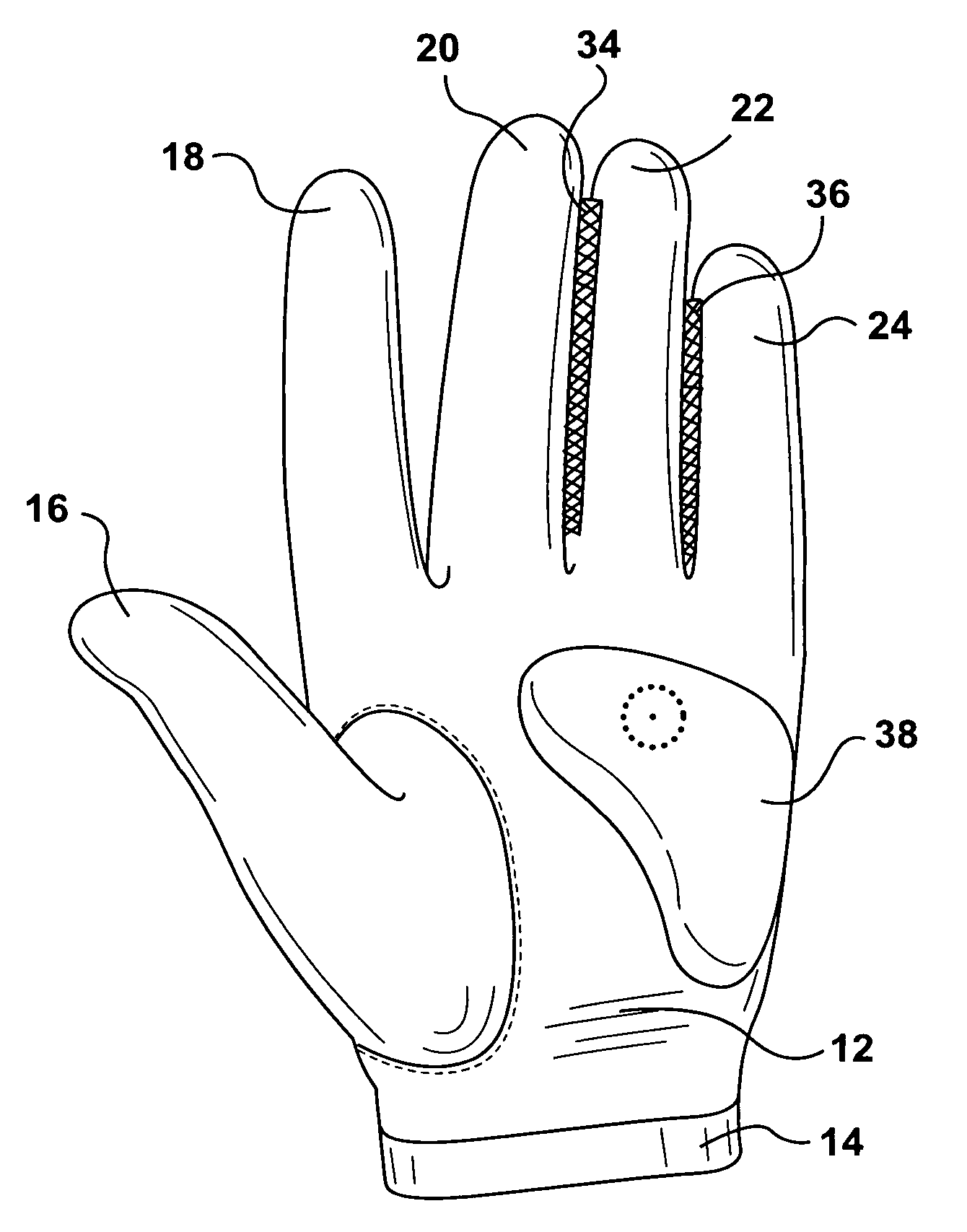
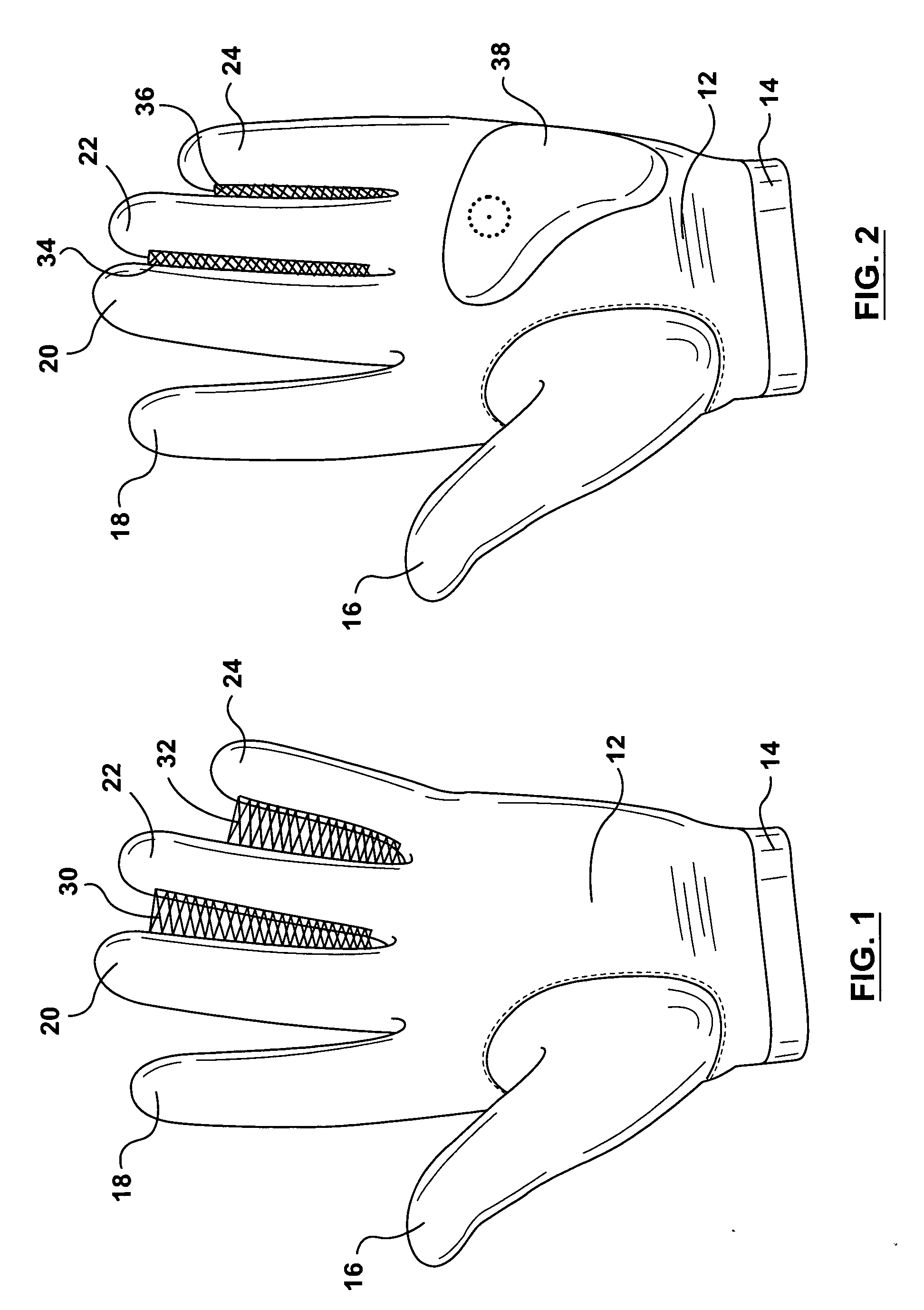
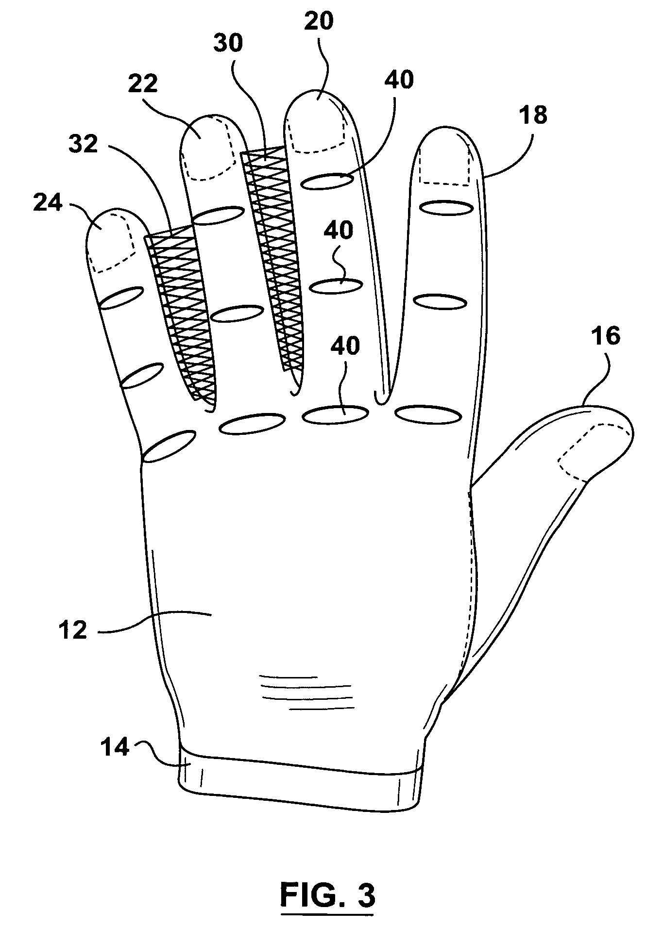
[0012] Referring first to FIG. 1 of the drawings, a golf glove has a palm receiving portion 12 with a hand receiving open end provided with a cuff 14. The glove also has a separate thumb receiving portion 16 and four separate finger receiving portions 18, 20, 22 and 24. As so far described, the golf glove is conventional.

[0013] In accordance with one embodiment of the invention, the second and third finger portions 20, 22 are connected over substantially all their length by a web portion 30. Similarly, the third and fourth finger portions 22, 24 are connected by a web portion 32. The web portions 30, 32 in accordance with the invention provide the wearer with better control of a golf club during the swing involved in hitting the ball.

[0014] The golf glove shown in FIG. 2 is basically the same as the golf glove shown in FIG. 1 and the same reference numerals are used for similar parts. However, in this embodiment, the web portions 34, 36 between the second and third finger portions...


PUM


Abstract

A golf glove has four separate finer receiving portions and a separate thumb receiving portion. Counting from the thumb receiving portion, the second and third finger portions and / or the third and fourth finger portion are secured to each other over a substantial part of their length.

Description

RELATED APPLICATION [0001] This invention claims priority from U.S. Provisional Patent Application No. 60 / 706019 filed Aug. 8, 2005.FIELD OF INVENTION [0002] This invention relates to golf gloves. BACKGROUND OF INVENTION [0003] Most golfers wear gloves on one hand only when they are hitting a golf ball with a club. Right handed golfers wear a glove on their left hand and left handed golfers wear a glove on their right hand. This has become conventional, it being believed that using a single glove in this manner gives better control of the club. A glove is usually not worn while using a putter, it being believed in this case that when putting it is preferable for both hands to directly contact the putter. [0004] It is very well know that, even for professionals, it is difficult to consistently hit a golf ball with a club in an effective manner. There are many reasons for this. One reason may be that conventional gloves fail to enable a golfer to grip the club in the best manner possi...

Claims


Application Information

Patent Timeline
Patent Type & Authority Applications(United States)
IPC IPC(8): A41D19/00
CPCA63B71/146
Inventor PARK, KEY-SOON
Owner PARK KEY SOON
Why Eureka
Try Eureka