
Portable magnifier for hand-held portable electronic device

a portable electronic device and portable technology, applied in the field of magnifiers, can solve the problems of difficult viewing of the foregoing popular hand-held portable electronic devices by vehicle operators, compounded problems, and difficulty in viewing the display of hand-held portable electronic devices, and achieve the effect of facilitating viewing of the display

Inactive Publication Date: 2007-02-15
BENDROR JACK +2
View PDF2 Cites 23 Cited by
  • Summary
  • Abstract
  • Description
  • Claims
  • Application Information

AI Technical Summary

Benefits of technology

[0010] It is, therefore, an object of the present invention to provide a portable magnifier which facilitates viewing of a display of a portable electronic device.
[0011] It is another object of the present invention to provide a portable magnifier which is self-supporting and adjustable so that the size of the information displayed on a display of a portable electronic device can be readily magnified.
[0012] It is another object of the present invention to provide a portable magnifier which can be easily and readily removably attached to a portable electronic device for magnifying information displayed on a display of the portable electronic device.
[0013] It is another object of the present invention to provide a portable magnifier for hand-held portable electronic device which is easy to assemble and inexpensive to purchase, so that the portable magnifier can readily be acquired by persons of modest means.
[0015] It still another object of the present invention to provide a portable magnifier for a hand-held portable electronic device that can be conveniently carried and stored.
[0016] It is still another object of the present invention to provide a portable magnifier which is highly durable and resistant to structural or performance degradation.

Problems solved by technology

However, the display of the foregoing popular hand-held portable electronic devices may be difficult for a user to view for several reasons.
If the user has poor eye sight due to age, illness, infirmity or otherwise, these problems are compounded.
Another problem arises when the hand-held portable electronic devices are mounted in holders or mounting structures in vehicles, such as motor vehicles, airplanes and boats.
The display of such hand-held portable electronic devices may be difficult for a vehicle operator to view because of the distance from the operator to the holder.
This problem can be compounded by miniaturization of the hand-held portable electronic devices and the correspondingly decreasing size of displays as set forth above.
However, this poses problems in ergonomics, structural integrity, and reliability.
If an enlarged LCD is mounted in a manner which allows it to protrude from the housing, the criteria of maintaining structural integrity, high reliability, and acceptable ergonomics cannot be met.
Unfortunately, the addition of character enlarging circuitry increases the complexity of electronic devices and increases manufacturing costs.
Furthermore, less information can be displayed within a given display area when characters are enlarged within the display.
However, these configurations are inconvenient to use, particularly when magnification of the displays of the hand-held portable electronic devices is not necessary.
For example, magnification of a display of a hand-held portable electronic device at close distance may be unnecessary and may be distracting to a user.
However, such an approach tends to be cumbersome because it does not leave the hands of the user free to perform other tasks, such as writing, during the viewing process because hand-held magnifying lenses require continuous support and manipulation by the user.

Method used


Image

  • Portable magnifier for hand-held portable electronic device
  • Portable magnifier for hand-held portable electronic device
  • Portable magnifier for hand-held portable electronic device

Examples


Embodiment Construction

[0032] While this invention is susceptible of embodiments in many different forms, this specification and the accompanying drawings disclose only some forms as examples of the use of the invention. The invention is not intended to be limited to the embodiments so described, and the scope of the invention will be pointed out in the appended claims.

[0033] Certain terminology is used in the following description for convenience only and is not intended to be limiting. The words outwardly, forward, rearward, downwardly and upstanding designate directions in the drawing to which reference is made. Such terminology includes the words above specifically mentioned and words of similar import.

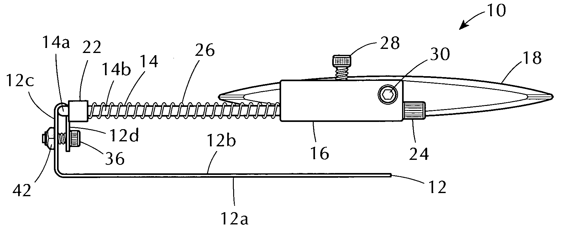
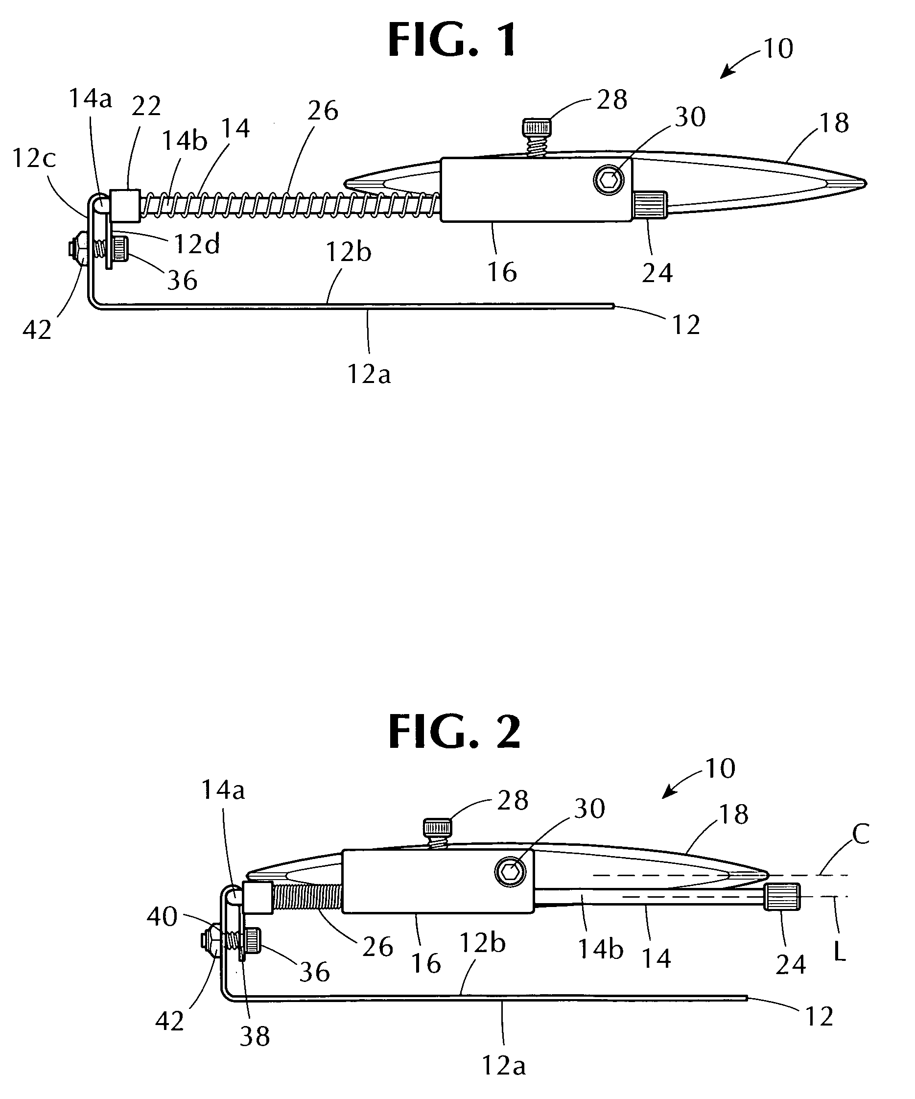
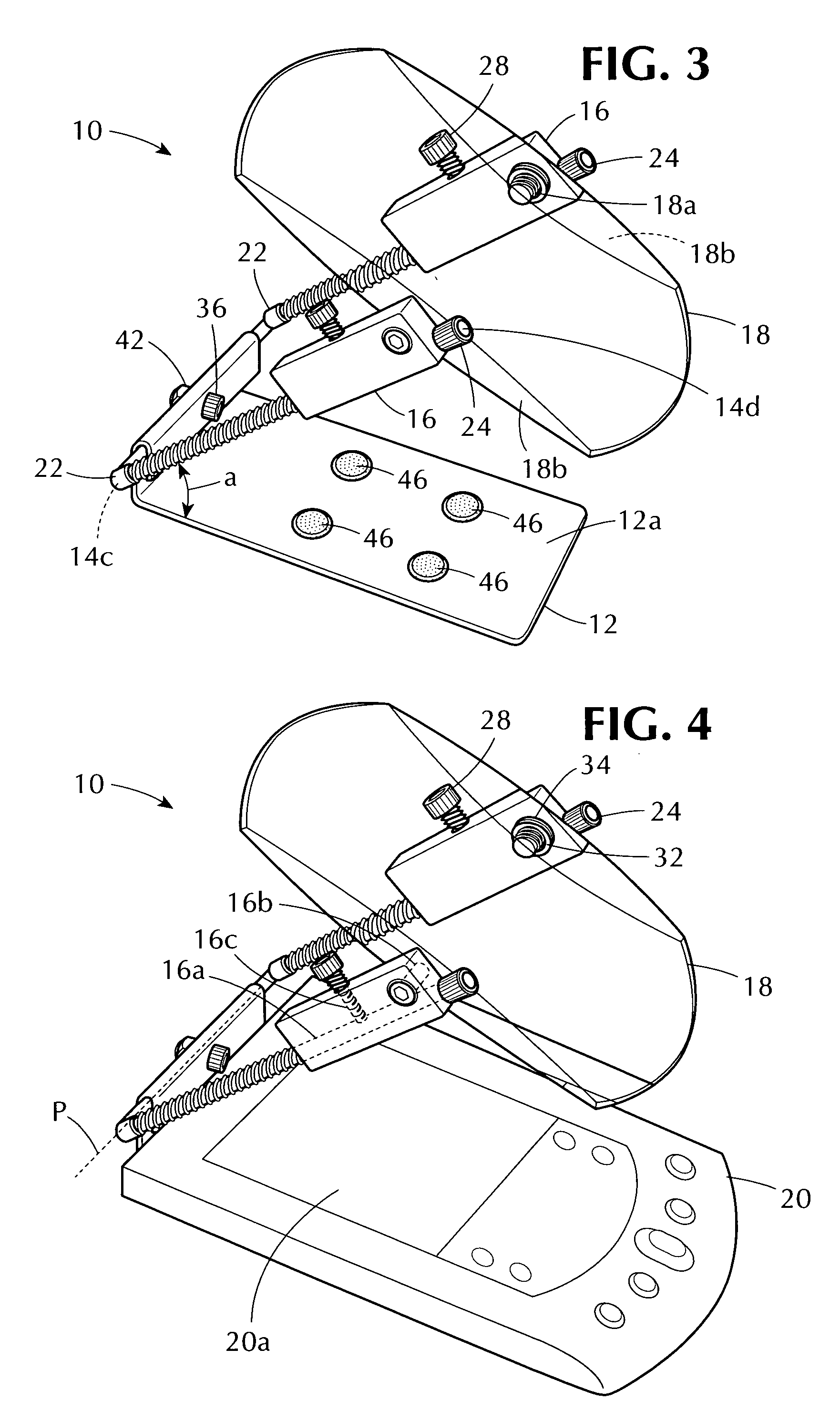
[0034] Referring now to the drawings in detail, wherein like numerals are used to indicate like elements throughout, there is shown in FIGS. 1-5 an embodiment of a portable magnifier, generally designated at 10, according to the present invention. FIG. 1 shows the portable magnifier 10 in a partially ...


PUM


Abstract

A portable magnifier has a support member having a support surface for removably supporting a portable electronic device having a display. A holder has a pair of holding portions and is connected to the support member for undergoing pivotal movement relative to the support surface of the support member. An optical element is mounted on the holding portions of the holder for undergoing sliding movement therealong. The optical element is also detachably pivotally connectable to the holding portions at preselected positions therealong to define a viewing state in which the optical element can be manually pivoted to a desired viewing position so that a user of the portable magnifier can view through the optical element a magnified version of information displayed on a display of the portable electronic device supported by the support surface of the support member.

Description

BACKGROUND OF THE INVENTION [0001] 1. Field of the Invention [0002] The present invention relates to magnifiers and, more specifically, to a portable magnifier for hand-held portable electronic devices, such as portable digital assistants (PDAs), personal organizers, global positioning system (GPS) units, palm-top computers, and portable electronic game devices. The present invention also relates to an apparatus for supporting a portable electronic device and equipped with an optical element for magnifying indicia displayed on a display of the portable electronic device. [0003] 2. Background of the Invention [0004] Hand-held portable electronic devices have become increasingly popular for both personal and commercial use. With their increase in popularity, hand-held portable electronic devices and their information display have also been undergoing miniaturization to facilitate storage and portability. Examples of popular hand-held portable electronic devices incorporating a display...

Claims


Application Information

Patent Timeline
Patent Type & Authority Applications(United States)
IPC IPC(8): G02B27/02
CPCG02B25/005
Inventor BENDROR, JACKSIRIS, MICHAEL J.LINES, KEN
Owner BENDROR JACK
Learn More