Imaging system, in particular a projection objective of a microlithographic projection exposure apparatus

a projection objective and exposure apparatus technology, applied in the field of imaging systems, can solve the problems of incomplete compensation achieved with the aforementioned “clocking” and a degree of intrinsic birefringence, and achieve the effect of reducing the negative effect of birefringence on image quality

Inactive Publication Date: 2007-02-15
WM WRIGLEY JR CO +1
View PDF8 Cites 10 Cited by
  • Summary
  • Abstract
  • Description
  • Claims
  • Application Information

AI Technical Summary

Benefits of technology

The patent describes how an improved imaging system can be used for microlithographic projections without being negatively affected by birefringence (when light passes through different parts of the optics). This means that higher refractive index crystals can be utilized which would otherwise have limited their usefulness due to this issue.

Problems solved by technology

The technical problem addressed in this patent relates to reducing the impact of intrinsic birefringence in high refractive index materials used in microlithography objectives. Birefringence causes latexial ray deflections that negatively affect the quality of the optical image being projected. Current methods involving arranging multiple fluoride crystal lenses in specific ways have been developed but may still result in incomplete compensation of birefringence when different compensation paths exist.

Method used


Image

  • Imaging system, in particular a projection objective of a microlithographic projection exposure apparatus
  • Imaging system, in particular a projection objective of a microlithographic projection exposure apparatus
  • Imaging system, in particular a projection objective of a microlithographic projection exposure apparatus

Examples


Embodiment Construction

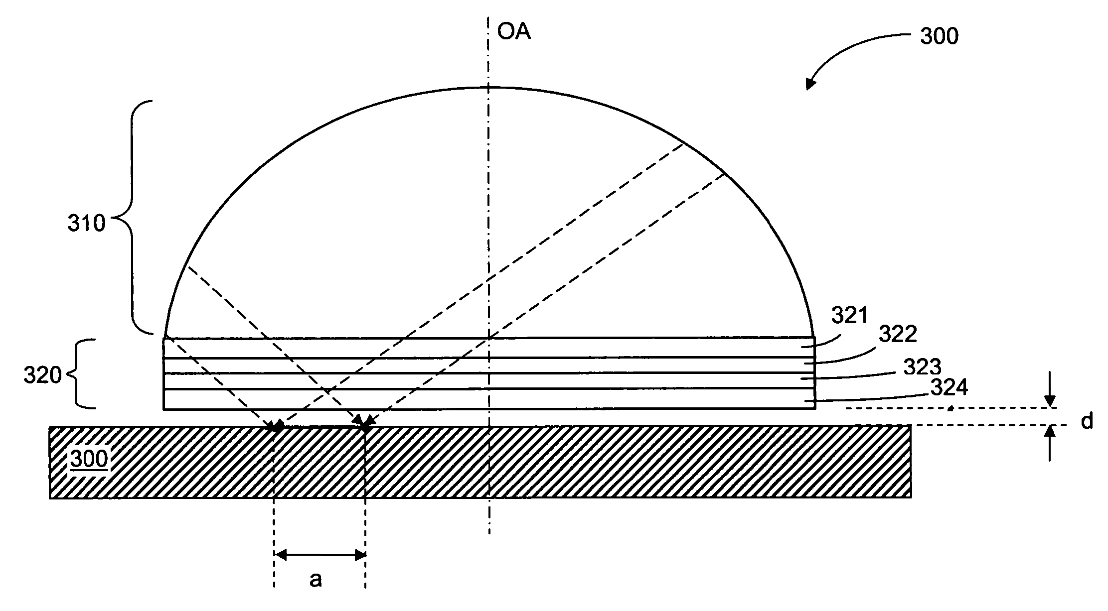
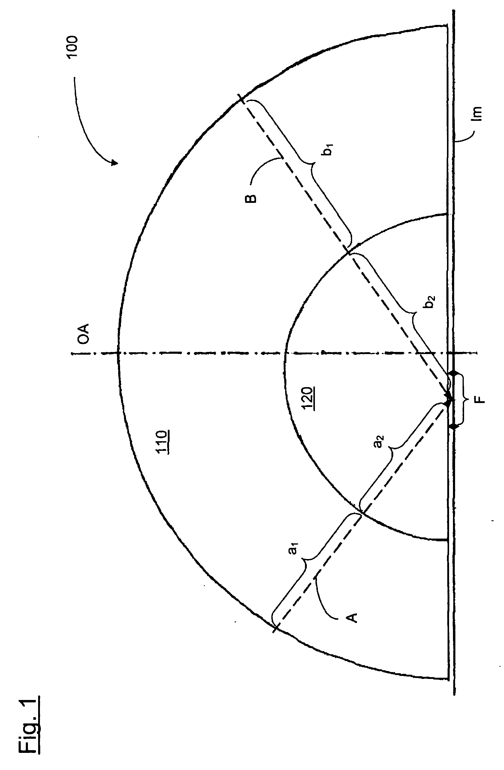
[0061] In a merely schematic manner, FIG. 1 shows the design structure of an optical element 100 in an imaging system according to the invention in accordance with a first preferred embodiment. With preference, the optical element 100 is in particular the last lens on the image side in a microlithographic projection objective whose principal design structure remains to be explained hereinafter in the context of FIG. 4.

[0062] Preferably, the imaging system is a catadioptric projection objective in which according to FIG. 1 (in a merely schematic representation that is not true to scale) an off-axis image field “F” (i.e., lying outside of the optical axis “OA”) is produced in an image plane “Im”. According to FIG. 1, the last optical element on the image side is a planar-convex lens 100 which in regard to its optical outside surface is rotationally symmetric relative to the optical axis OA. However, as shown schematically in FIG. 1, the planar-convex lens is composed of elements 110 ...


PUM


Abstract

Imaging systems, in particular a projection objectives of a microlithographic projection exposure apparatus, are provided. The imaging systems can have an optical axis and produce an image field which is extra-axial relative to the optical axis. The imaging systems can include a first optical element which causes a first distribution of the retardation in a plane that lies perpendicular to the optical axis, and at least one second optical element which causes a second distribution of the retardation in a plane that lies perpendicular to the optical axis. The second distribution of the retardation can at least partially compensate the first distribution of the retardation. The first and the second optical elements can be designed without rotational symmetry relative to the optical axis.

Description


Claims


Application Information

Patent Timeline
Owner WM WRIGLEY JR CO
Why Eureka
Try Eureka