
Joystick sensor with light detection

a joystick and light detection technology, applied in the field of manual control, can solve the problems of requiring the magnet movement of the magnetic sensor in a relatively complex manner, and reducing so as to achieve the effect of reducing or eliminating the disadvantages of existing joysticks and improving the mobility of the occupants

Inactive Publication Date: 2007-02-15
DELPHI TECH INC
View PDF18 Cites 24 Cited by
  • Summary
  • Abstract
  • Description
  • Claims
  • Application Information

AI Technical Summary

Benefits of technology

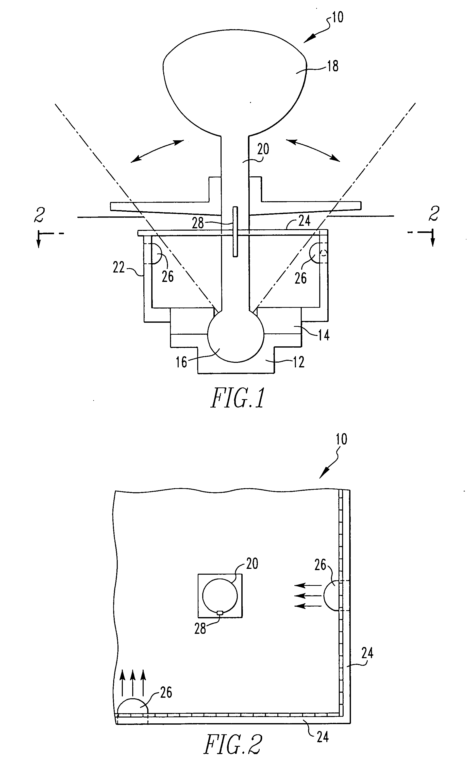
[0007] In order to meet this need, the present invention provides a specialized system of light detection of the relative motion of the shaft of a joystick, including traditional joystick angularized rotation around a point along its axis as well as true axial rotation of the joystick in its vertical position. Among the light sources and lenses which enable the light detection and the optical nature of the light sensors, wear surfaces in the joystick are minimized or eliminated everywhere except, where applicable, in the universal joint at the base of certain joystick designs. The specialized system includes two one-dimensional light sensors, such as without limitation CCD or CMOS or other sensors, mounted at right angles to one another, which together define the x and y axis of a virtual sensor plane through which the joystick shaft extends perpendicularly. Regardless of the joystick's location, the joystick registers both an “x” and a “y” location on each one-dimensional light sensor, respectively, which location signal and the subsequent change in location signal creates a guidance vector. Additionally, the two one-dimensional sensor arrays can register whether the shaft of the joystick has rotated about its own axis, as long as the joystick shaft is optically variegated at the portion of the joystick shaft which intersects the sensor plane so that the extent and direction of rotation of the shaft can be optically discerned. The above combined sensing options make it possible to create true forward / back, side-to-side and rotational vectors via a joystick. In wheelchair applications, the separate forward / back, side-to-side and rotational vectors can translate into improved occupant mobility, especially when all four wheels of the wheelchair can be guided according to the joystick vectors.

Problems solved by technology

Virtually all if not all of the existing joysticks are replete with disadvantages inherent in their mechanical and electromagnetic designs.
Magnetic sensors require movement of magnets in a relatively complex manner and are vulnerable to interference from outside magnetic fields.
Resistive sensors require movement of the wiper along a resistive surface, with inevitable unwanted wear at the contact surfaces.
Multiple parts make for large devices and undesirably high costs including the labor required for assembly.

Method used


Image

  • Joystick sensor with light detection
  • Joystick sensor with light detection
  • Joystick sensor with light detection

Examples


Embodiment Construction

)

[0015] The present invention creates a virtual sensor plane by arraying two one-dimensional light sensors at right angles to one another wherein the shaft of a joystick extends perpendicularly through the virtual sensor plane. With this configuration, the sensor plane can detect traditional joystick rotation around a point along its axis as well as a herein-disclosed true rotation of the joystick around the joystick axis itself. Between the light sources and lenses which enable light detection and the optical, rather than mechanical or electromechanical, nature of the light sensors, wear surfaces in the joystick are minimized or eliminated everywhere except, where applicable, in the universal joint at the base of joystick configurations which include such a universal joint. The light sensors may be CCD sensors or CMOS sensors, as nonlimiting examples. Regardless of the joystick's location, the joystick registers both an “x” and a “y” location on each one-dimensional light sensor, r...


PUM


Abstract

The present invention creates a virtual sensor plane by arraying two one-dimensional light sensors at right angles to one another wherein the shaft of a joystick extends perpendicularly through the virtual sensor plane. With this configuration, the sensor plane can detect traditional joystick rotation around a point along its axis as well as a herein-disclosed true rotation of the joystick around the joystick axis itself. Between the light sources and lenses which enable light detection and the optical, rather than mechanical or electromechanical, nature of the light sensors, wear surfaces in the joystick are minimized or eliminated everywhere except, where applicable, in the universal joint at the base of joystick configurations which include such a universal joint.

Description

BACKGROUND OF THE INVENTION [0001] 1. Field of the Invention [0002] This invention relates to manual controls of the joystick type useful in the operation of motorized wheelchairs. The manual controls can have application in other technologies as well, including but not limited to vehicles besides wheelchairs, video games and training simulators. [0003] 2. Description of Related Art [0004] Motorized wheelchairs are becoming more and more common, and typically they are guided by what are referred to as “joystick” controls. Ordinarily, a graspable handle is pivotally mounted for universal rotation around a point along its axis and sensors are provided to identify the angle of tilt along the perpendicular axes through the point of rotation. Numerous sensing schemes have been used, such as potentiometers in contact with brushes that move corresponding to the tilt of the joystick (see U.S. Pat. No. 4,856,785 and No. 6,259,433). Some joystick sensors harness the interaction of induction c...

Claims


Application Information

Patent Timeline
IPC IPC(8): G09G5/08
CPCG05G9/047G05G2009/04759
Inventor VOTO, ANDREWSELBY, RONALDPERRY, KENNETHROSS, DAVIDDUMSA, ALFREDLIPPMANN, RAYCHEN, YANSONG
Owner DELPHI TECH INC
Learn More