
Dual power protective device for power supply

a protective device and power supply technology, applied in padlocks, building locks, constructions, etc., can solve the problems of unsatisfactory design anti-theft functions, complex three-dimensional arrangement, and inadequate design anti-theft purposes, and achieve the effect of optimal anti-theft effects

Inactive Publication Date: 2007-02-15
LIU SHUN MING
View PDF26 Cites 30 Cited by
  • Summary
  • Abstract
  • Description
  • Claims
  • Application Information

AI Technical Summary

Benefits of technology

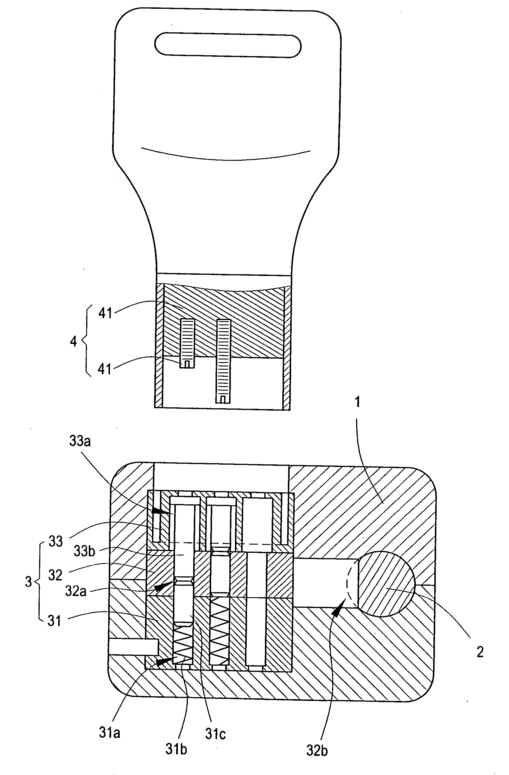
[0008] Therefore, an object of the invention is to provide a lock cylinder having an unlocking mechanism consisted of a fixed cylindrical block, a lock cylinder core and a pressing pin cylindrical block, wherein an inserting pin of a key is inserted into the orifice at the spring pin cylindrical block to push a spring pin into an orifice of the fixed cylindrical block, thereby unlocking and locking using a fastening bolt by turning the lock cylinder core for obtaining an optimal anti-theft effect.

Problems solved by technology

Such designs are rather inadequate in anti-theft purposes for that these designs are commonly used and easily opened by thieves using thin and sharp objects.
This three-dimensional arrangement is more complicated than the aforesaid planar arrangement, however, the balls yet act as the pressing and engagement element of the password thereof.
Also, this design has unsatisfactory anti-theft functions because the balls disposed in column-shaped distributions have even more exposure to the exterior and are thus likely to be unlocked by thieves using thin and sharp objects.

Method used


Image

  • Dual power protective device for power supply
  • Dual power protective device for power supply
  • Dual power protective device for power supply

Examples


Embodiment Construction

[0015] To better understand the invention, descriptions shall be given with the accompanying drawings hereunder.

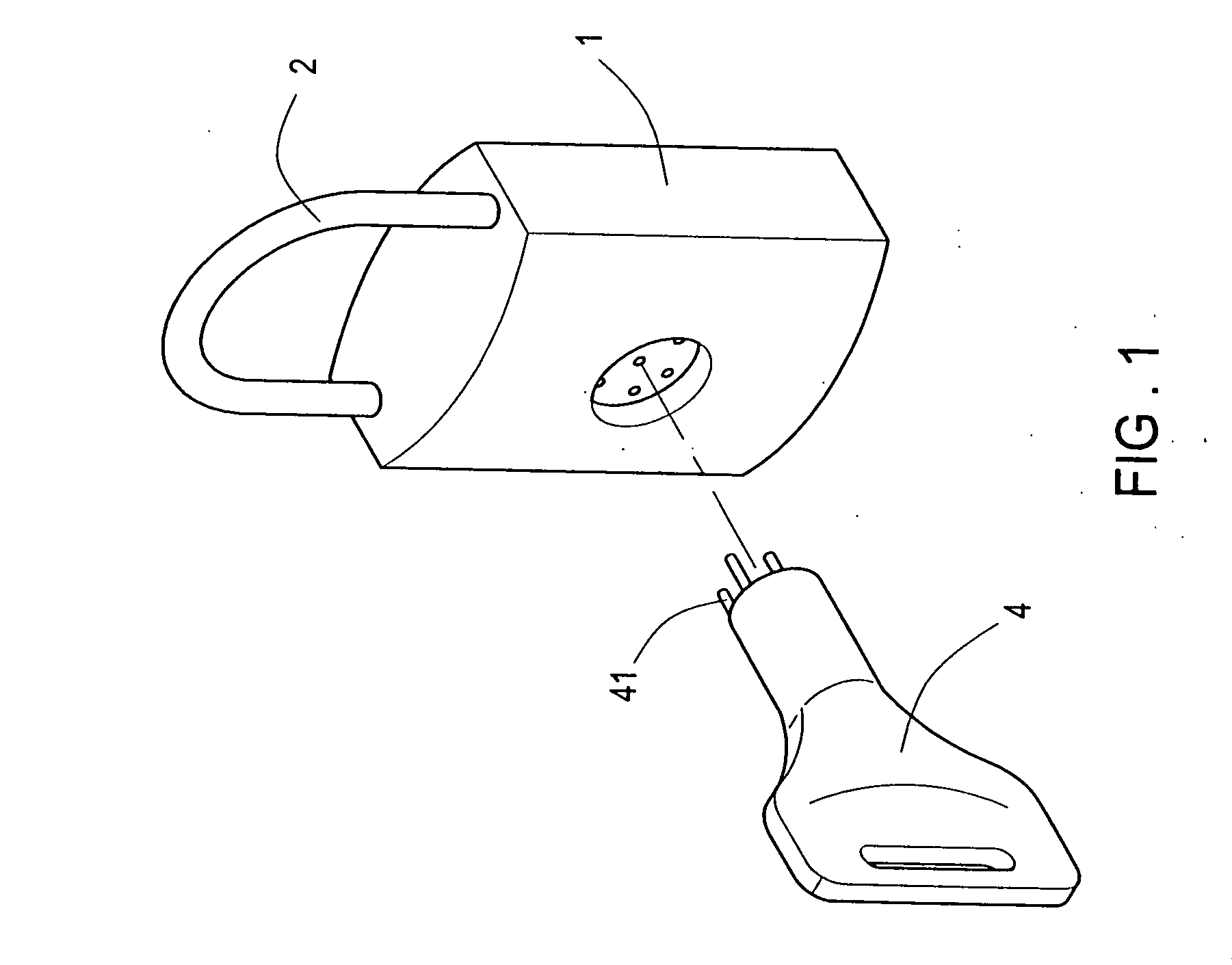
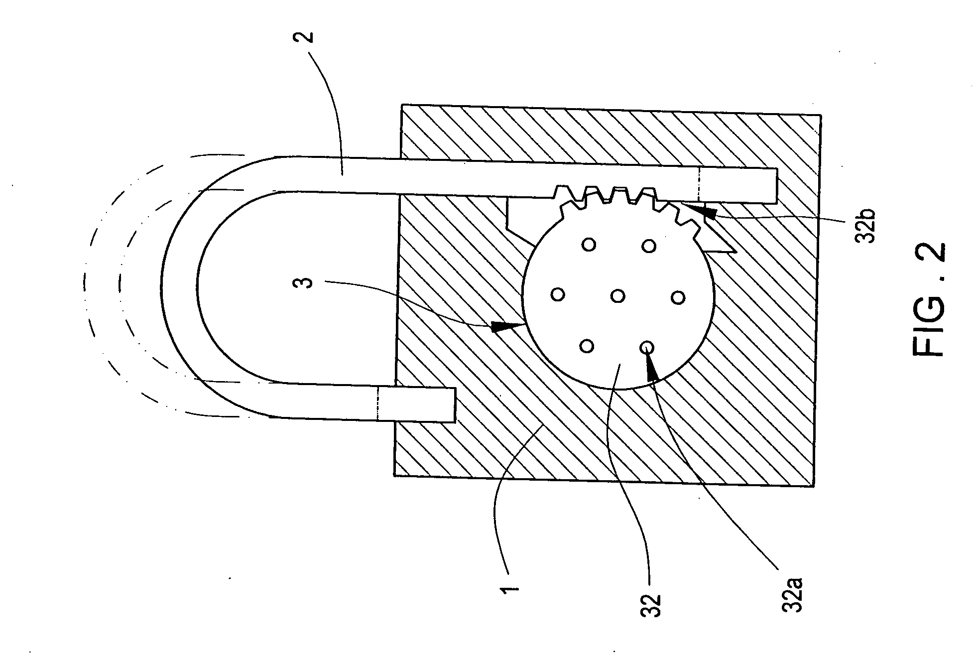
[0016] Referring to FIGS. 1, 2 and 3, the invention comprises a housing 1 disposed with a sliding fastening bolt 2, and an unlocking mechanism 3 provided in the housing 1; a key 4 is inserted into the unlocking mechanism 3 and turned for impelling sliding movements of the fastening bolt 2 so as to unlock; and the characteristics thereof are: [0017] the unlocking mechanism 3 is consisted of a fixed cylindrical block 31, a lock cylinder core 32 and a pressing pin cylindrical block 33; wherein the fixed cylindrical block 31, the lock cylinder core 32 and the pressing pin cylindrical block 33 are provided with a plurality of corresponding orifices 31a, 32a and 33a, respectively; a portion of the orifices 31a at the fixed cylindrical block 31 is provided with spring pins 31c pressed against by springs 31b, and the spring pins 31c are partially or entirely extended into the ori...


PUM


Abstract

A lock cylinder includes a sliding fastening bolt, and an unlocking mechanism disposed in a housing. The characteristics thereof are that the unlocking mechanism is consisted of a fixed cylindrical block, a lock cylinder core and a pressing cylindrical block that are all provided with a plurality of corresponding orifices, respectively. A portion of the orifices at the fixed cylindrical block and the pressing pin cylindrical block is provided with spring pins and a pressing pin respectively. The lock cylinder core further impels the fastening bolt by an interlocking mechanism while a key is provided with an inserting pin for inserting into the orifice at the pressing cylindrical block to push the pressing pin inward that further pushes the spring pin into the orifice at the fixed cylindrical block, thus further turning the lock cylinder core and impelling the sliding fastening bolt for unlocking and obtaining an optimal anti-theft effect.

Description

BACKGROUND OF THE INVENTION [0001] (a) Field of the Invention [0002] The invention relates to a lock cylinder, and more particularly, to a lock cylinder comprising an unlocking mechanism consisted of a fixed cylindrical block, a lock cylinder core and a pressing pin cylindrical block, wherein an inserting pin of a key is inserted into an orifice at a spring pin cylindrical block to push a spring pin into an orifice of the fixed cylindrical block, thereby unlocking and locking the structure using a fastening bolt by turning the lock cylinder core. [0003] (b) Description of the Prior Art [0004] Common headlocks, bell locks or door locks, in principle, comprise a fastening bolt capable of up-and-down sliding movements and an unlocking mechanism disposed within a housing thereof. The unlocking mechanism is interlocked with the fastening bolt to lock windows or doors; whereas a key is inserted into the unlocking mechanism that subsequently releases the fastening bolt to unlock. [0005] Pr...

Claims


Application Information

Patent Timeline
Patent Type & Authority Applications(United States)
IPC IPC(8): E05B27/08
CPCE05B19/18E05B67/24E05B45/10E05B27/083Y10T70/7593
Inventor LIU, SHUN-MING
Owner LIU SHUN MING
Learn More