
Multiple stage web material processor

a web material processor and multi-stage technology, applied in the direction of paper/cardboard wound articles, etc., can solve the problems of limiting the minimum strength of paperboard used to manufacture paperboard cores, affecting the quality of paperboard cores, and unable to easily unravel the composite tube formed from several layers, etc., to achieve consistent and controllable tension

Inactive Publication Date: 2007-02-08
GEORGIA PACIFIC CONSUMER PRODS LP
View PDF22 Cites 3 Cited by
  • Summary
  • Abstract
  • Description
  • Claims
  • Application Information

AI Technical Summary

Benefits of technology

[0010] The present invention is directed towards a spiral wound tube. Spiral wound tubes comprising a single ply of paper web material may be formed by the method and apparatus herein described. In one embodiment, the method comprises steps of providing a mandrel, a single ply of web material, and a web processor. An adhesive binding agent is applied to a portion of the web material as it is drawn through the web processor according to the invention. The web processor provides a consistent and controllable tension to the web material as it is drawn onto the mandrel during the tube forming operation.

Problems solved by technology

Although each of the spirally wound layers includes a continuous helical seam, the composite tube formed from several layers does not readily unravel because the seams in adjacent paperboard layers are offset radially from each other as mentioned above, and because of the substantial surface bonding between adjacent tube layers.
Such applicators tend to be relatively bulky and require routine maintenance.
There is a limit to the minimum strength of paperboards that can be used to manufacture paperboard cores.
Thus, the cores cannot be made from materials which are so thin and / or weak that they will not form a self-supporting structure upon being wound into helical form because the tube structure must provide support to the sheet material which is wound onto the core.
It is often difficult to properly bond the overlapped joint.
Improper bonding often results in tube having a single continuous helical seam which is apt to unravel.
It has also been found in practice that a uniform and properly bonded overlapped joint is particularly difficult to achieve when attempts are made to form single ply tubes from paperboard plies.
If either of these conditions are not met, the paperboard tube can have an uneven, wrinkled appearance and / or will not be uniformly bonded along the overlapping joint.

Method used


Image

  • Multiple stage web material processor
  • Multiple stage web material processor
  • Multiple stage web material processor

Examples


Embodiment Construction

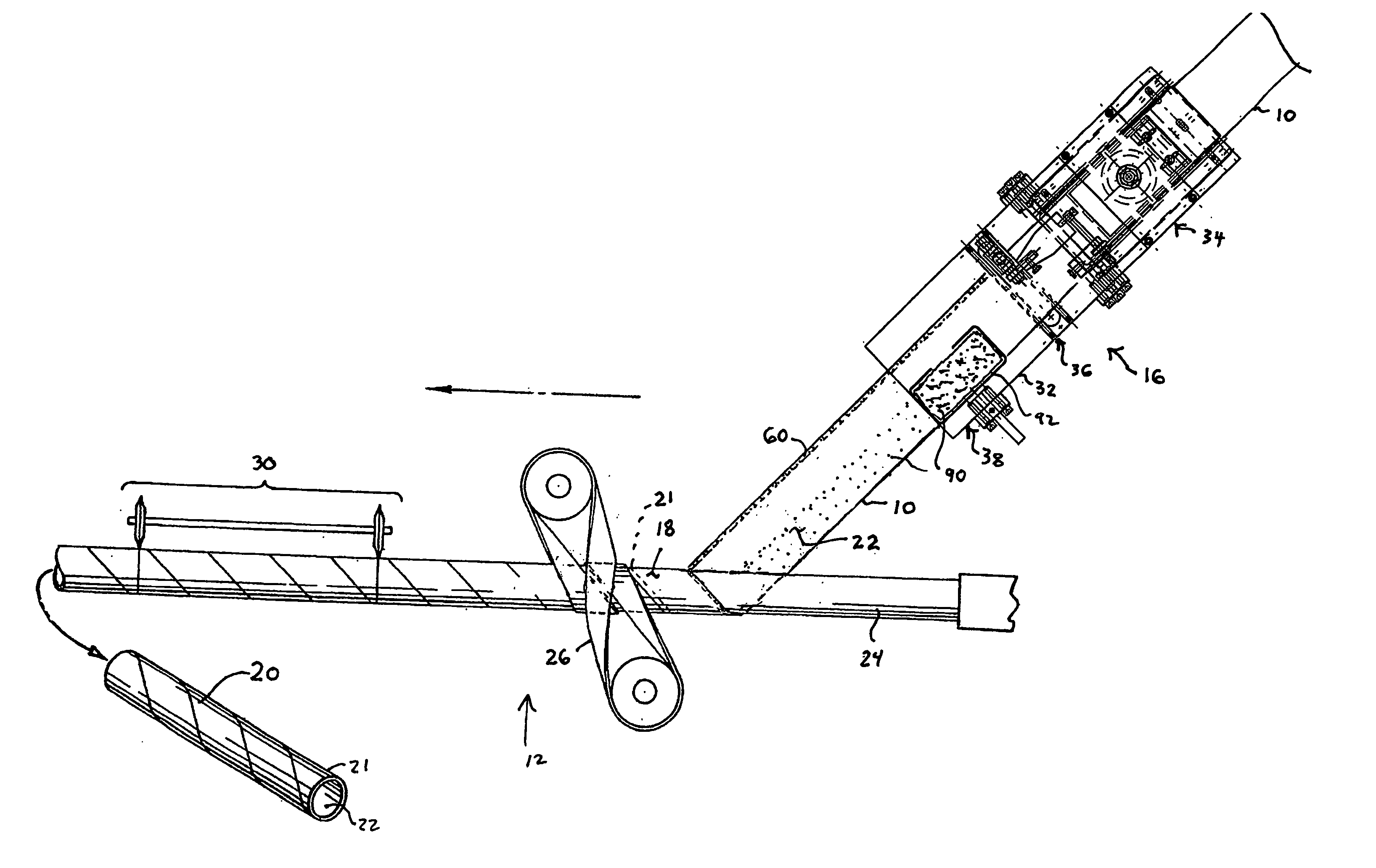
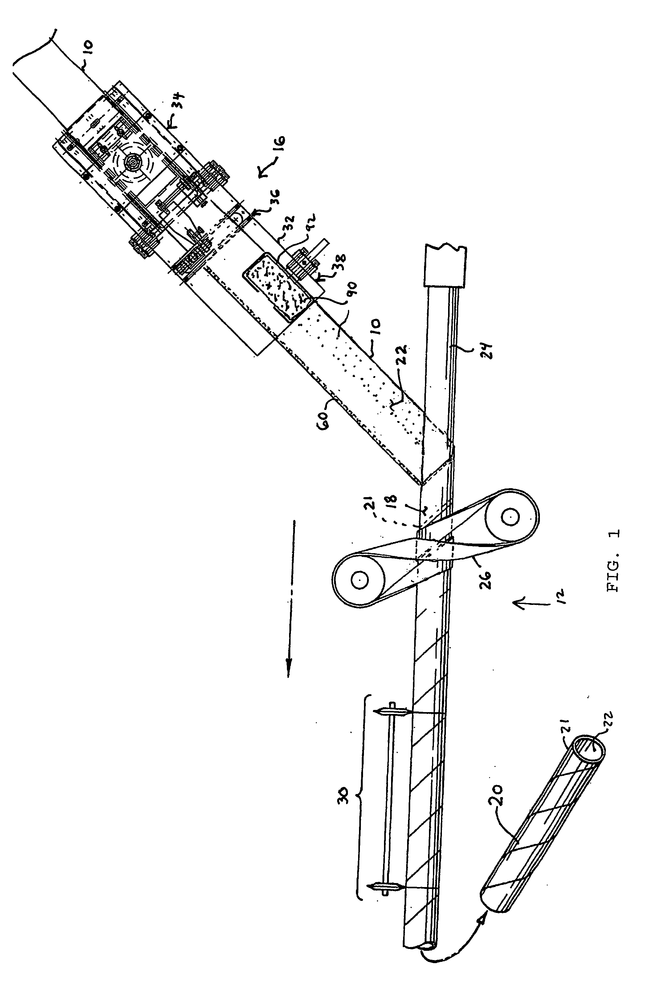
[0020] As illustrated in FIG. 1, web material 10 is provided to a winding apparatus 12 from a parent or supply roll (not shown). Prior to being introduced to winding apparatus 12, web material 10 passes through a web processor 16. The length of the web material 10 is substantially greater than the width or thickness of the material. The web material 10 has a first surface 18 that forms the outer surface of the wound tube 20 and a second surface 22 that forms the inner surface of the wound tube 20. An overlap region 21 is defined adjacent to a lateral edge of the web material 10. As described in more detail herein, an adhesive is applied within the overlap region 21 during the tube forming process. Depending on the particular operating environment, the adhesive may be supplied on either the outer surface 18 or inner surface 22 of wound tube 20.

[0021]FIG. 1 schematically illustrates one preferred process for forming a continuous paperboard tube from a continuous web 10. Generally, th...


PUM


Abstract

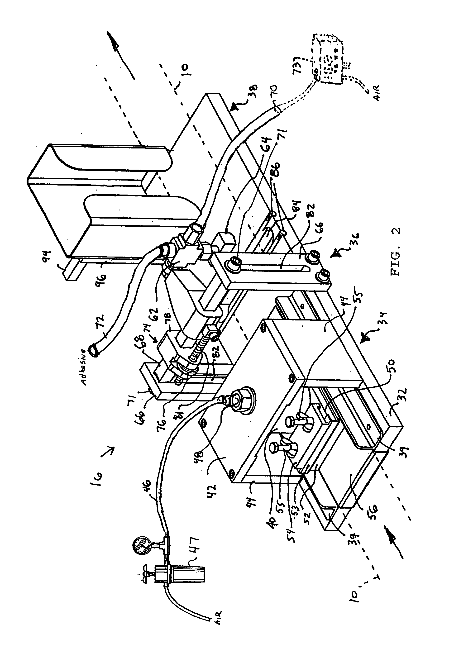
A multiple stage web processor including a tensioning stage and a gluing stage. The tensioning stage includes an air bag which generates a normal force applied against the web material. Web material tension may be altered with a change in air bag pressure. The gluing stage includes an adhesive applicator and provides an adhesive along a portion of the web material surface and also applies a second normal force and tension to the web material. Together the tensioning stage and the gluing stage provide a controlled tension to the web material as the web material is drawn through the apparatus and wrapped around a tube-forming mandrel. The web processor may include a lubrication stage applying a lubricant to the web material surface. A method of forming a core from a web material with a web processor is disclosed.

Description

TECHNICAL FIELD [0001] The present invention relates to spiral wound tubes. More particularly, this invention relates to ply handling equipment, particularly for high speed spiral wound tubes, and to methods and apparatuses for winding such tubes. BACKGROUND OF THE INVENTION [0002] Spiral wound paper tubes are well known. Disposable sheet goods such as bath tissue, paper towels, gift wrap, aluminum foil and the like, are often sold in the form of a roll supported by a tubular paperboard core. Because of the strength required in the paperboard core during the process of winding the disposable sheet goods onto the core, the core has normally been formed of at least two radially superposed layers, which in turn, are formed from separate spirally wound paperboard plies. Each of the spirally wound paperboard plies forms a helical seam which extends in the axial direction along the paperboard tube and which results from abutment of the opposed longitudinally extending edges of the ply alo...

Claims


Application Information

Patent Timeline
Patent Type & Authority Applications(United States)
IPC IPC(8): B31C11/04
CPCB31C3/00
Inventor VENUTI, ALAN
Owner GEORGIA PACIFIC CONSUMER PRODS LP
Learn More