
Back-lit displays with high illumination uniformity

a back-lit display and uniform illumination technology, applied in the field of optic displays, can solve the problems of lcd-tvs with different viewing angles, lcd monitors and hand-held devices, and inconvenient illumination profiles,

Inactive Publication Date: 2007-02-08
3M INNOVATIVE PROPERTIES CO
View PDF68 Cites 52 Cited by
  • Summary
  • Abstract
  • Description
  • Claims
  • Application Information

AI Technical Summary

Benefits of technology

The invention is about a display unit that uses a light source to produce illumination light. A diffuser layer is placed between the light source and the display panel, and a brightness enhancing layer or reflective polarizer is added between the diffuser layer and the display panel. A light-diverting surface is also added between the diffuser layer and the light source. This surface helps to direct the illumination light towards the display panel. The technical effect of this invention is to improve the brightness and clarity of the display by using a diffuser layer and a brightness enhancing layer or reflective polarizer. Additionally, the light-diverting surface helps to direct the illumination light towards the display panel, further improving the display's quality.

Problems solved by technology

In addition, the viewing angle requirements for LCD-TVs are generally different from those for LCD monitors and hand-held devices.
Such an illumination profile is not desirable, and so a diffuser plate is typically used to smooth the illumination profile at the back of the LCD device.
These plates often deform or warp after exposure to the elevated temperatures of the lamps.
They are expensive to manufacture, and increase manufacturing costs, since the diffusing pattern must be registered to the illumination source at the time of assembly.
In addition, the diffusion plates require customized extrusion compounding to distribute the diffusing particles uniformly throughout the polymer matrix, which further increases costs.

Method used


Image

  • Back-lit displays with high illumination uniformity
  • Back-lit displays with high illumination uniformity
  • Back-lit displays with high illumination uniformity

Examples


Embodiment Construction

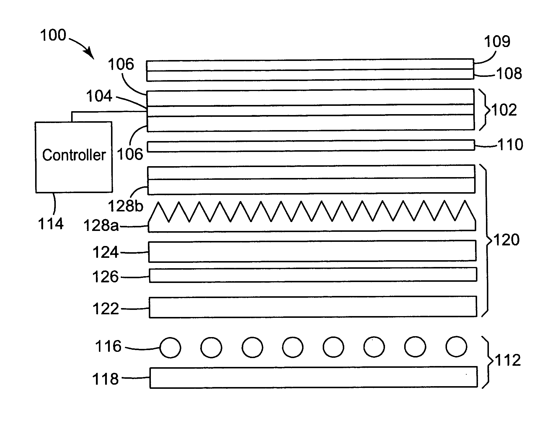
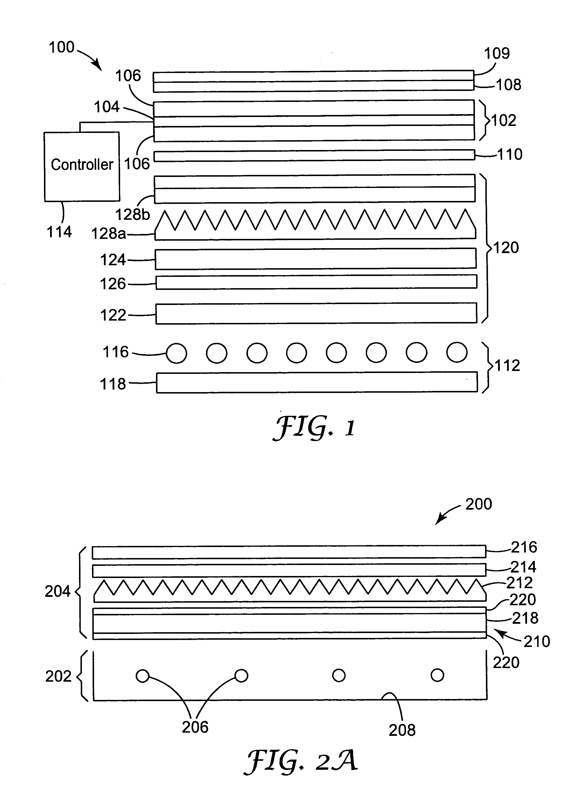
[0032] The present invention is applicable to display panels, such as liquid crystal displays (LCDs, or LC displays), and is particularly applicable to LCDs that are directly illuminated from behind, for example as are used in LCD monitors and LCD televisions (LCD-TVs). More specifically, the invention is directed to the management of light generated by a direct-lit backlight for illuminating an LC display. An arrangement of light management films is typically positioned between the backlight and the display panel itself. The arrangement of light management films, which may be laminated together or may be free standing, typically includes a diffuser plate and a brightness enhancement film having a prismatically structured surface.

[0033] A schematic exploded view of an exemplary embodiment of a direct-lit display device 100 is presented in FIG. 1. Such a display device 100 may be used, for example, in an LCD monitor or LCD-TV. The display device 100 may be based on the use of an LC ...


PUM

PropertyMeasurementUnit
thickaaaaaaaaaa
apex angleaaaaaaaaaa

Abstract

A directly illuminated display unit has a light source unit that includes one or more light sources capable of producing illumination light for illuminating a display panel. A diffuser layer is disposed between the light source unit and the display panel. At least one of a first brightness enhancing layer and a reflective polarizer is disposed between the diffuser layer and the display panel. A light-diverting surface is disposed between the diffuser layer and the light source unit. The light-diverting surface diverts a propagation direction of at least some of the illumination light passing from the light source unit to the diffuser layer.

Description

FIELD OF THE INVENTION [0001] The invention relates to optical displays, and more particularly to liquid crystal displays (LCDs) that are directly illuminated by light sources from behind, such as may be used in LCD monitors and LCD televisions. BACKGROUND [0002] Some display systems, for example liquid crystal displays (LCDs), are illuminated from behind. Such displays find widespread application in many devices such as laptop computers, hand-held calculators, digital watches, televisions and the like. Some backlit displays include a light source that is located to the side of the display, with a light guide positioned to guide the light from the light source to the back of the display panel. Other backlit displays, for example some LCD monitors and LCD televisions (LCD-TVs), are directly illuminated from behind using a number of light sources positioned behind the display panel. This latter arrangement is increasingly common with larger displays because the light power requirement...

Claims


Application Information

Patent Timeline
Patent Type & Authority Applications(United States)
IPC IPC(8): G02F1/1335
CPCG02B5/045G02F2001/133607G02F1/133611G02F1/133606G02F1/133607G02F1/1335
Inventor EPSTEIN, KENNETH A.
Owner 3M INNOVATIVE PROPERTIES CO
Learn More