Imaging apparatus, imaging method and recording medium for minimizing release time lag

Inactive Publication Date: 2007-02-08
RICOH KK
View PDF19 Cites 15 Cited by
  • Summary
  • Abstract
  • Description
  • Claims
  • Application Information

AI Technical Summary

Benefits of technology

[0023] It is, therefore, an object of the present invention to provide an imaging apparatus capable of minimizing a release time lag and having a low cost by setting highly the maximum of control in a high shutter speed.
[0024] Specifically, the present invention intends to provide an imaging apparatus in which when a shutter speed for recording a subject is more than a predetermined time, an electronic shutter term is shifted and then a timing of a mechanical shutter is started to shorten a release time lag totally.
[0027] As a result, the present invention makes it possible to shorten a release time lag and to prevent an upper limit in a high shutter speed from being limited owing to a performance of the mechanical shutter.

Problems solved by technology

In addition, an error due to a delay by the mechanical shutter is compensated by micro-adjustment of the electronic shutter.
However, in the prior art as described above, even though an exposure mode is established by a blanking term or the like being completed, there is a problem that there is a time lag resulting from the micro-adjustment of the electronic shutter until an actual exposure is initiated and therefore it is not possible to photograph an subject moving with a super high speed, for example.
As a result, there is a problem that the maximum of control in a high shutter speed becomes low in the prior art.
In this way, when the shutter speed is high, the exposure time for recording an image becomes short.

Method used


Image

  • Imaging apparatus, imaging method and recording medium for minimizing release time lag
  • Imaging apparatus, imaging method and recording medium for minimizing release time lag
  • Imaging apparatus, imaging method and recording medium for minimizing release time lag

Examples


Embodiment Construction

[0041] An embodiment of the present invention will be explained with reference to the accompanying drawings below.

[0042] It should be noted that the present invention is not limited to the embodiment, and various modification and changes can be made with respect to the embodiment.

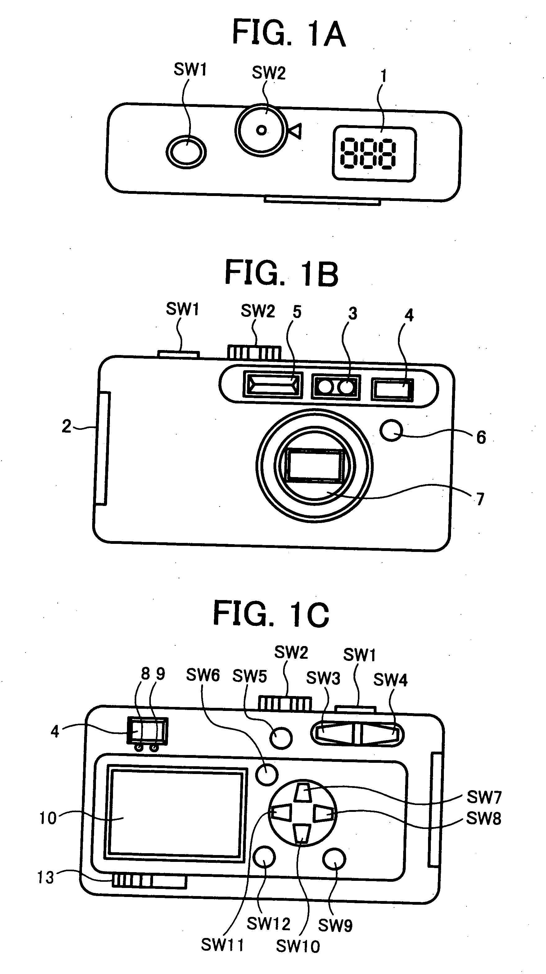
[0043] Referring to FIGS. 1A and 1B, a digital camera is shown as one example of an imaging apparatus according to the present invention.

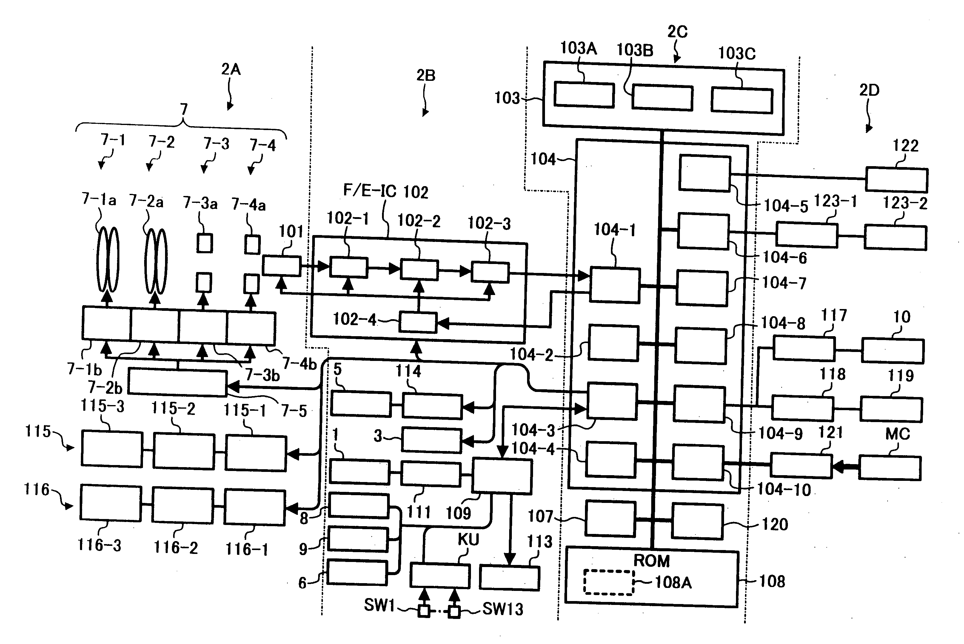
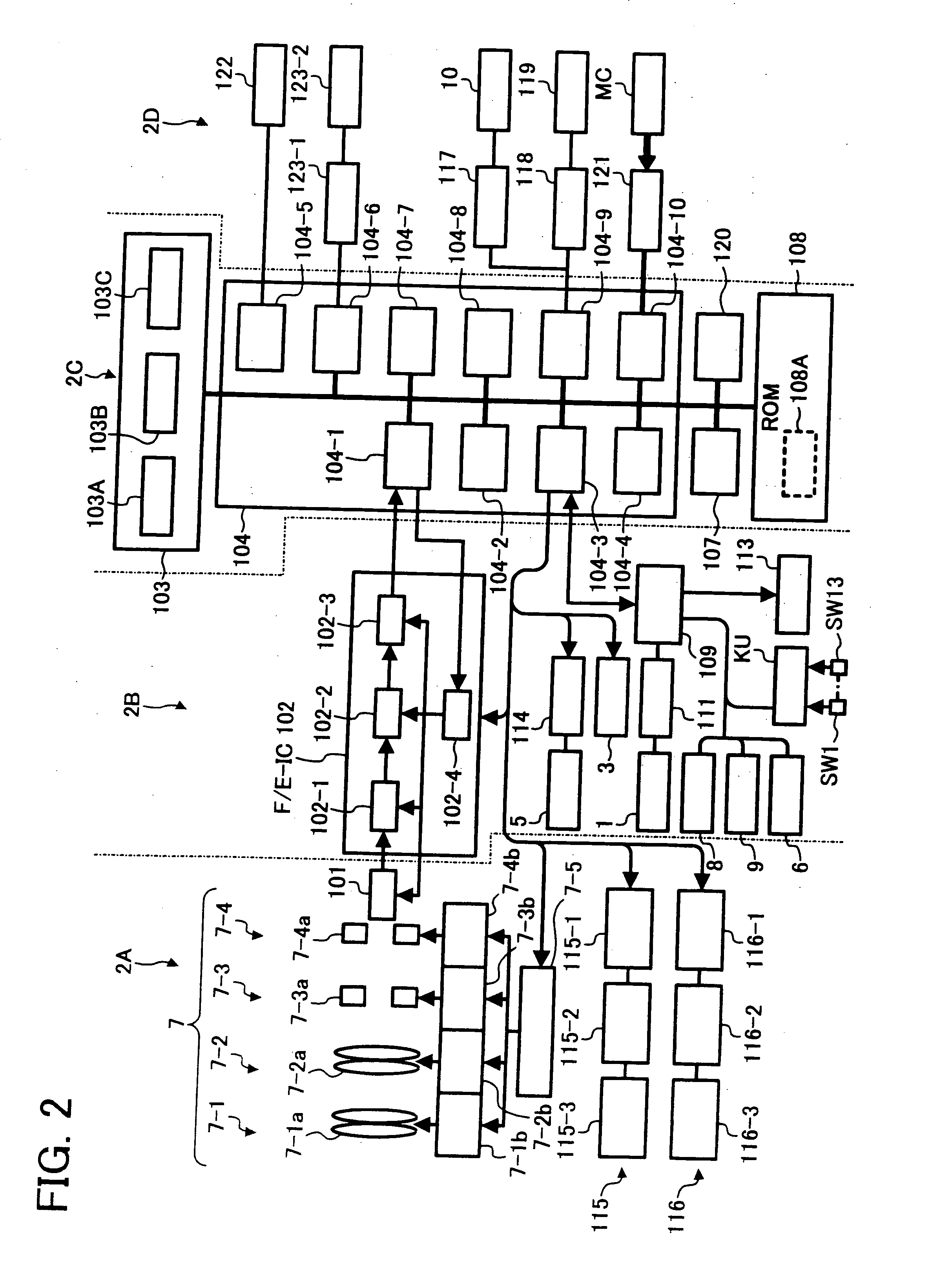
[0044] As shown in FIG. 1A, a release shutter SW1, a mode dial SW2 and a sub LCD 1 are provided on a top surface of the digital camera. Also, as shown in FIG. 1B, a SD card and a battery lid 2, a ranging unit 3, an optical finder 4, a strobe light emitting part 5, a remote control light receiving part 6 and a lens barrel unit 7 are provided on a front surface of the digital camera.

[0045] Further, as shown in FIG. 1C, an AF LED 8, a strobe LED 9 and a LCD monitor 10 are provided on a back surface of the digital camera. In addition, provided on the back surface of the di...


PUM


Abstract

An imaging apparatus comprises a device for discharging charge or F / E-IC (102) for discharging charge accumulated in an imaging device or CCD (101) and for canceling exposure in a discharging term of the charge, a light shielding device or mechanical shutter unit (7-4) for a mechanical shutter (7-4a), which shields light by the mechanical shutter (7-4a), and a control device or CPU block (104-3) for hastening by a predetermined time the charge discharging term of the CCD (101) in the discharging device (102) and a light shielding timing of the mechanical shutter (7-4a) in the light shielding device (7-4), when a shutter speed for recording a subject is more than a predetermined time.

Description

CROSS-REFERENCE TO THE RELATED APPLICATIONS [0001] This application is a continuation of U.S. application Ser. No. 10 / 764,449, filed Jan. 27, 2004 and claims the benefit of priority under 35 U.S.C. § 119 from Serial No. 2003-031678, filed Feb. 7, 2003 and Ser. No. 2003-427668, filed Dec. 24, 2003, the entire contents of each which are incorporated herein by reference.BACKGROUND OF THE INVENTION [0002] 1. Field of the Invention [0003] The present invention relates to an imaging apparatus, an imaging method and a recording medium capable of minimizing a time (hereinafter referred to as release time lag) until an actual exposure is initiated, after a release shutter button is pressed. [0004] 2. Description of the Prior Art [0005] Generally, means for controlling an exposure time of an imaging device or a light-receiving device such as a CCD are classified in the following two kinds in a digital camera. [0006] One is a mechanical shutter for shielding physically radiation of light from ...

Claims


Application Information

Patent Timeline
IPC IPC(8): H04N5/335H04N5/232G03B9/08H04N5/235H04N5/353H04N5/372H04N101/00
CPCH04N5/2353H04N5/232H04N23/73
Inventor OJIMA, NORIAKIKITAJIMA, TATSUTOSHISUGIURA, KOHICHINAKAHIRA, TOSHIAKIYOSHIDA, AKIHIRO
Owner RICOH KK
Why Eureka
Try Eureka