
Error factor acquisition device, method, program, and recording medium

a technology of error factor and acquisition device, applied in the field of measurement of error factor, can solve problems such as complicated operations

Inactive Publication Date: 2007-02-08
ADVANTEST CORP
View PDF1 Cites 17 Cited by
  • Summary
  • Abstract
  • Description
  • Claims
  • Application Information

AI Technical Summary

Benefits of technology

[0010] According to the error factor acquisition device of the present invention, the first state realization unit may include: an open-circuit calibration tool that realizes an open-circuit state; a short-circuit calibration tool that realizes a short-circuit state; a standard load calibration tool that realizes a standard load state; a short-circuiting unit that short-circuits the output port and the reception port; an output port connection unit that connects any one of the open-circuit calibration tool, the short-circuit calibration tool, the standard load calibration tool, and the short-circuiting unit to the output port; and a reception port connection unit that connects any one of

Problems solved by technology

Upon the calibration, there poses a problem that the number of the attachments and detachments of the calibration kits increases, resulting in complicated operations.

Method used


Image

  • Error factor acquisition device, method, program, and recording medium
  • Error factor acquisition device, method, program, and recording medium
  • Error factor acquisition device, method, program, and recording medium

Examples


first embodiment

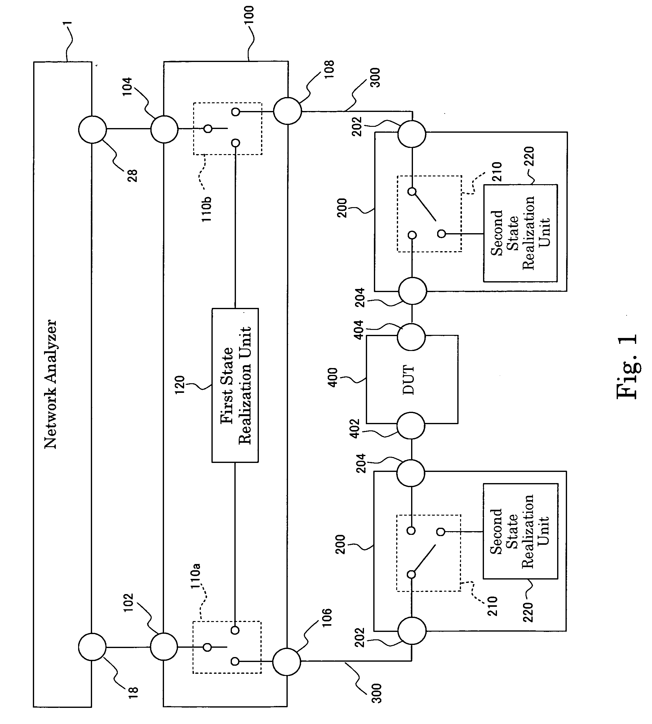
[0038]FIG. 1 is a diagram showing a configuration of a measurement system in which an error factor acquisition device according to a first embodiment of the present invention is used. The measurement system is provided with a network analyzer 1, a first calibrator 100, second calibrators 200, cables 300, and a DUT 400. The first calibrator 100 and the second calibrators 200 constitute the error factor acquisition device.

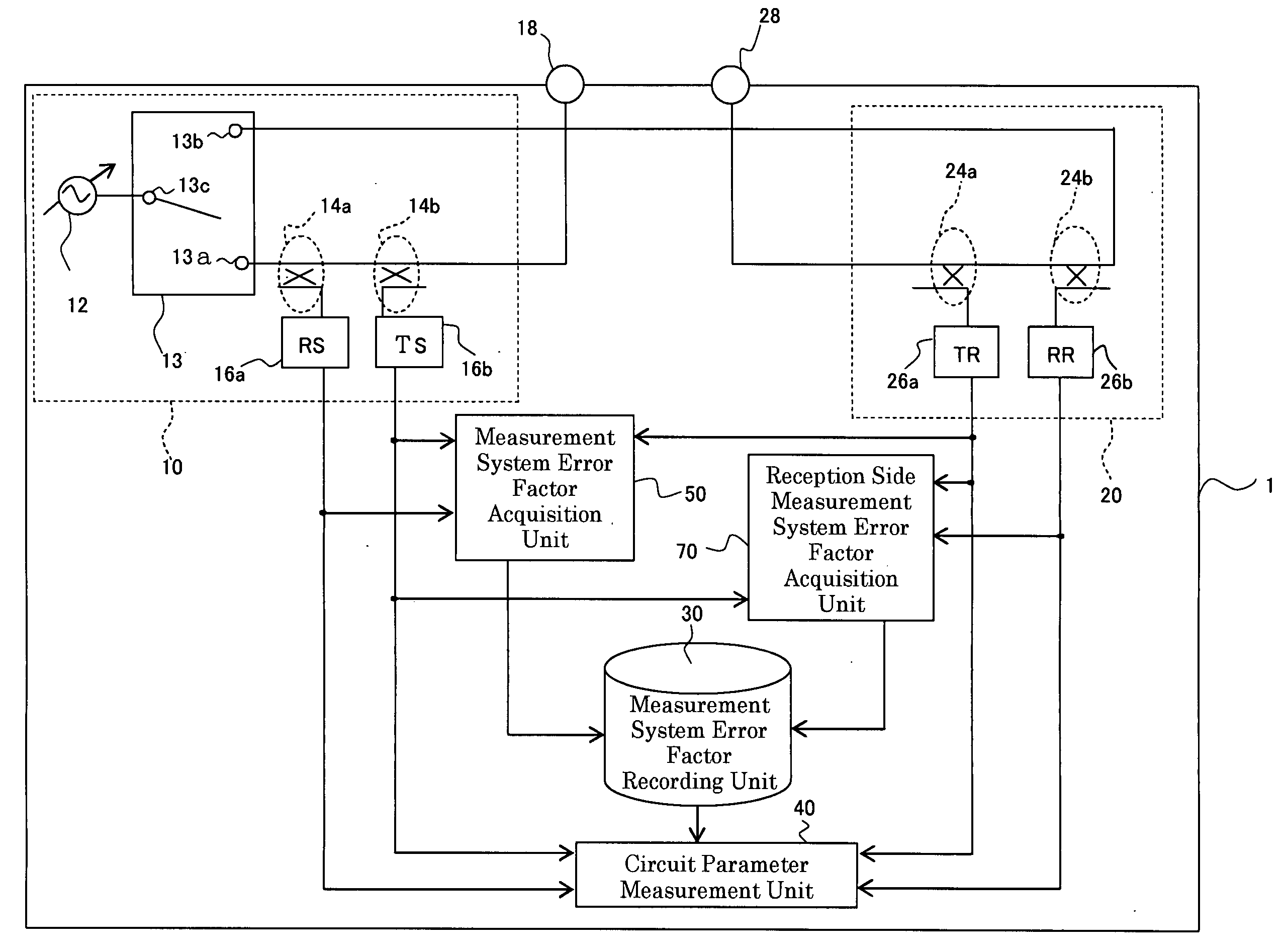
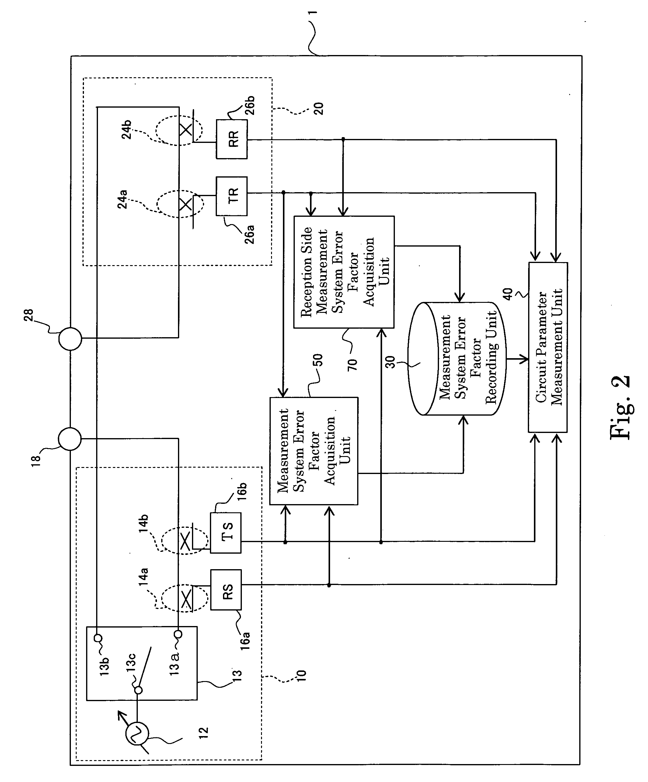
[0039]FIG. 2 shows a configuration of the network analyzer 1. The network analyzer 1 is provided with a signal source 10, a reception means 20, a measurement system error factor recording unit 30, a circuit parameter measurement unit 40, a measurement system error factor acquisition unit 50, a reception side measurement system error factor recording unit 70.

[0040] The signal source 10 is provided with a signal output unit 12, a switch 13, bridges 14a and 14b, a receiver (RS) 16a, a receiver (TS) 16b, and a port 18.

[0041] The signal output unit 12 outputs an input ...

second embodiment

[0099] A second embodiment is different from the first embodiment in that the numbers of the ports of the network analyzer 1 and the DUT 400 according to the first embodiment are respectively increased to four.

[0100]FIG. 10 is a diagram showing a configuration of a measurement system in which an error factor acquisition device according to a second embodiment of the present invention is used. The measurement system is provided with the network analyzer 1, the first calibrator 100, the second calibrators 200, the cables 300, and the DUT 400. The first calibrator 100 and the second calibrators 200 constitute the error factor acquisition device. In the following section, similar components are denoted by the same numerals as of the first embodiment, and will be explained in no more details.

[0101] The network analyzer 1 is provided with ports 18, 28, 38, and 48. The internal configuration thereof is approximately the same as that of the first embodiment. A signal output from a certain...

third embodiment

[0118] According to a third embodiment, the number (nine) of the ports of the DUT 400 is larger than the number (four) of the ports of the network analyzer 1, and the third embodiment is different from the second embodiment in that the error factor acquisition device is further provided with a nine-port test set (branch connection means) 500.

[0119]FIG. 12 is a diagram showing a configuration of a measurement system in which the error factor acquisition device according to the third embodiment of the present invention is used. The measurement system is provided with a network analyzer 1, the first calibrator 100, the second calibrators 200, the cables 300, the DUT 400, and the nine-port test set 500. The first calibrator 100 and the second calibrators 200 constitute the error factor acquisition device. In the following section, similar components are denoted by the same numerals as of the second embodiment, and will be explained in no more details.

[0120] The network analyzer 1, the...


PUM


Abstract

It is possible to calibrate a measurement system for circuit parameters of a DUT (device under test) by reducing the number of attachments and detachments of calibration kits. An error factor acquisition device includes: a first calibrator (100) connected to ports (18, 28) of a network analyzer and having a first state realization unit (120) for realizing open-circuit, short-circuit, and standard load states for the ports (18, 28) or short-circuiting the ports (18, 28); and second calibrators (200) connected to the first calibrator (100) and the DUT (400) and respectively having a second state realization unit (220) for realizing open-circuit, short-circuit, and standard load states for the ports (18, 28). The first calibrator (100) includes first connection units (110a, 110b) for connecting the ports (18, 28) to the first state realization unit (120) or to the respective second calibrators (200) while the second calibrators (200) respectively include a second connection unit (210) for connecting the ports (18, 28) to the second state realization unit (220) or to the DUT (400).

Description

TECHNICAL FIELD [0001] The present invention relates to a measurement of error factors upon calculating and measuring circuit parameters of a device under test. BACKGROUND ART [0002] Conventionally, there have been measured circuit parameters (such as the S parameters) of a device under test (DUT) (refer to a patent document 1 (Japanese Laid-Open Patent Publication (Kokai) No. H11-38054, for example). A description will now be given of a measurement method of the circuit parameters of a device under test (DUT) according to the prior art with reference to FIG. 16. [0003] A signal is transmitted from a signal source 130 to a reception unit 140 via a DUT 400. The signal is received by the reception unit 140. It is possible to acquire the S parameters and frequency characteristics of the DUT 400 by measuring the signal received by the reception unit 140. [0004] On this occasion, measurement system errors are generated in the measurement due to mismatching between a measurement system su...

Claims


Application Information

Patent Timeline
IPC IPC(8): G01R23/16G01R27/28G01R35/00
CPCG01R35/005G01R27/28G01R35/00
Inventor HARUTA, MASATOSATO, HIROYUKITANABE, TAKESHINAKAYAMA, YOSHIKAZU
Owner ADVANTEST CORP
Learn More