
Anesthetizing chamber and microscope apparatus

anesthesia chamber and microscope technology, applied in the field of anesthesia chamber and microscope apparatus, can solve the problems of difficult to achieve a complete seal between the inhalation device and the nose of the small laboratory animal, and the leakage of anesthesia gas from this space, so as to prevent the leakage of anesthesia gas

Inactive Publication Date: 2007-02-08
OLYMPUS CORP
View PDF17 Cites 25 Cited by
  • Summary
  • Abstract
  • Description
  • Claims
  • Application Information

AI Technical Summary

Benefits of technology

[0007] The present invention was conceived in view of the above-described circumstances and has as its objective the provision of an anesthetizing chamber and microscope apparatus in which the leakage of anesthetic gas is prevented, and with which it is possible to observe a specimen such as a small laboratory animal in vivo over a long period of time.

Problems solved by technology

However, in such conventional inhalant anesthesia machines, it is difficult to achieve a complete seal of the space that is formed between the inhalant device and the small laboratory animal's nose and mouth.
As result, when observations are carried out over a long period of time while maintaining the animal in an anesthetized state, an undesirable situation results in which anesthetic gas leaks from this space.

Method used


Image

  • Anesthetizing chamber and microscope apparatus
  • Anesthetizing chamber and microscope apparatus
  • Anesthetizing chamber and microscope apparatus

Examples


first embodiment

[0024] The anesthetizing chamber 1 according to the present invention will now be explained with reference to FIGS. 1 and 2.

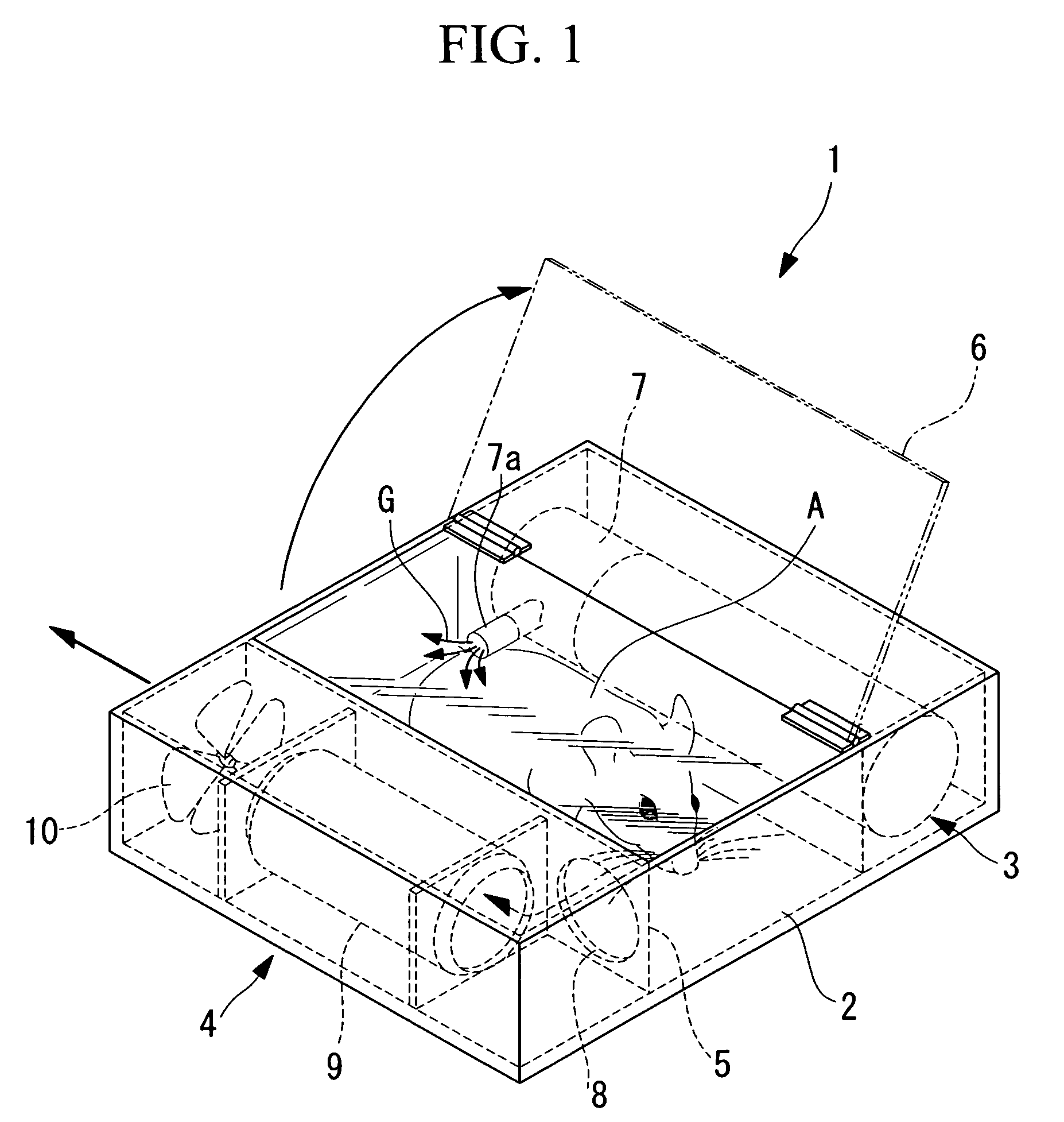
[0025] As shown in FIG. 1, the anesthetizing chamber according to this embodiment comprises a chamber main body 2 for housing a specimen A such as a laboratory animal; an anesthetic gas supply part 3 for supplying anesthetic gas G to the chamber main body 2; and an anesthetic gas recovery part 4 for recovering the anesthetic gas G that is supplied into the chamber main body 2 from the anesthetic gas supply part 3.

[0026] The inside of the chamber main body 2 is partitioned into a specimen housing 5 for housing the specimen A, an anesthetic gas supply part 3, and an anesthetic gas recovery part 4. A lid (window) 6 that can be opened and closed is provided to at least the specimen housing 5. Specimen A can be placed in or removed from the specimen housing 5 when the lid 6 is open.

[0027] The lid 6 of the specimen housing 5 is comprised of a plate that is made of ...

second embodiment

[0042] Next, the anesthetizing chamber 40 according to the present invention will be explained with reference to FIG. 3.

[0043] Note that in the following explanation, the same numeric symbols have been applied to parts that are equivalent to the structures of the anesthetizing chamber 1 according to the first embodiment explained above, and an explanation thereof is omitted here.

[0044] As shown in FIG. 3, the anesthetizing chamber 40 according to this embodiment comprises with a chamber main body 41 for housing a specimen A or other laboratory animal and an observation device 11 for observing the specimen A in an airtight manner; an anesthetic gas supply part 43 for supplying an anesthetic gas G into the chamber main body 41; and an anesthetic gas recovery part 44 for recovering the anesthetic gas G that leaks into the chamber main body 41.

[0045] The observation device 11 is a laser-scanning fluoroscopy device identical to that shown in FIG. 2, with only the observing head 15 hous...


PUM


Abstract

The present invention prevents the leakage of anesthetic gas, and enables in vivo observation of a specimen such as small laboratory animals over a long period of time. An anesthetizing chamber comprises a chamber main body for housing a specimen such as a laboratory animal; an anesthetic gas supply part for supplying anesthetic gas to the chamber main body; and an anesthetic gas recovery part for recovering the anesthetic gas that is supplied into the chamber main body from the anesthetic gas supply part; wherein a transparent window is provided to at least the chamber main body.

Description

BACKGROUND OF THE INVENTION [0001] 1. Field of the Invention [0002] This invention relates to an anesthetizing chamber and microscope apparatus used during microscopic observation of a specimen such as a small laboratory animal in vivo. [0003] This application is based on Japanese Patent Application No. 2005-229475, the content of which is incorporated herein by reference. [0004] 2. Description of Related Art [0005] Inhalant anesthesia machines for use with small laboratory animals have been developed in order to maintain the animal in a live state without causing pain when performing in vivo observation of a specimen such as the small laboratory animal. In these inhalant anesthesia machines, the nose and mouth of the mouse is covered with a bag-like inhalation device, and the small laboratory animal is placed in a somnolent, or anesthetized, state by supplying anesthetic gas into the inhalation device. (See S. A. Techno K.K., Yuzuru KURABAYASHI, Research Related to the Development ...

Claims


Application Information

Patent Timeline
IPC IPC(8): A61M15/00
CPCA01K1/031A61D7/04A22B3/005A22B3/00
Inventor TSUYUKI, KEITANIKAWA, YOSHIHISAKAWANO, YOSHIHIRO
Owner OLYMPUS CORP
Learn More