
Tandem axial piston pump unit

Active Publication Date: 2007-02-01
SA POCLAIN HYDRAULICS B P
View PDF10 Cites 14 Cited by
  • Summary
  • Abstract
  • Description
  • Claims
  • Application Information

AI Technical Summary

Benefits of technology

[0018] Another advantage of the present invention is an improvement of the dynamic behavior of the combustion engine and tandem pump connection when mounted in a machine frame or a vehicle chassis. Lifetime of the central bearing can also be increased.
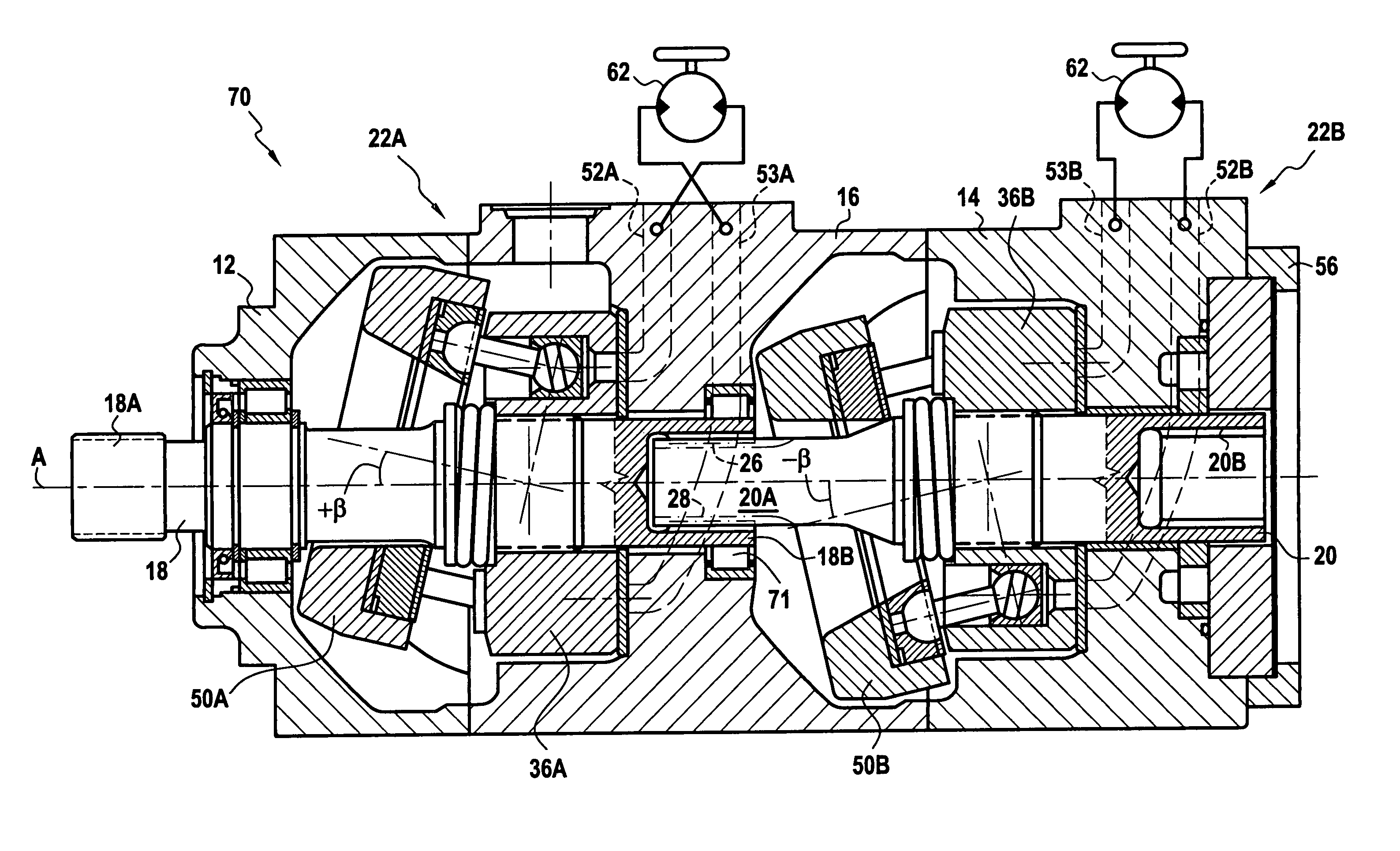
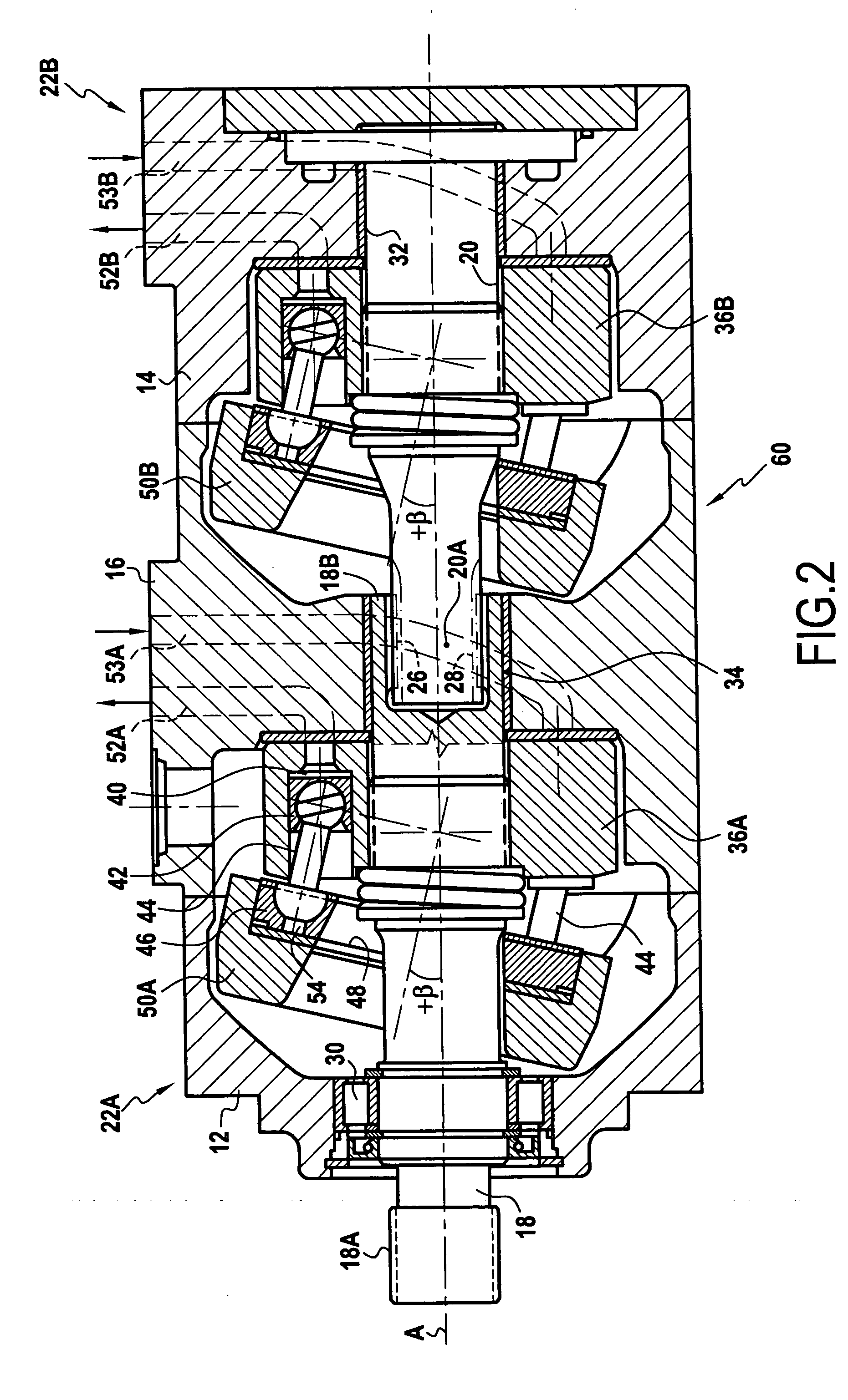
[0019] Due to the use of a single central bearing for both shafts, the overall length (Ls) of the tandem pump unit is shortened such that for equal displacements, the total length is significantly less than twice the length of a single pump of prior art design.

Problems solved by technology

One disadvantage of these arrangements relates to the large number of parts required for radial bearing of the shafts and for effecting torque transmission between them.
This results in increased manufacturing costs and the overall axial length of the tandem pump assembly is large.
The excessive length of the pump assembly adds to the overall weight of the pump unit, and hence requires additional material during production.
These factors contribute to increased manufacturing and operating costs of the pump unit.
However, such arrangements are suitable only for lower operating pressures and small displacements of the pumps.

Method used


Image

  • Tandem axial piston pump unit
  • Tandem axial piston pump unit
  • Tandem axial piston pump unit

Examples


Embodiment Construction

[0024] The invention will now be described by way of example with reference to the accompanying drawings.

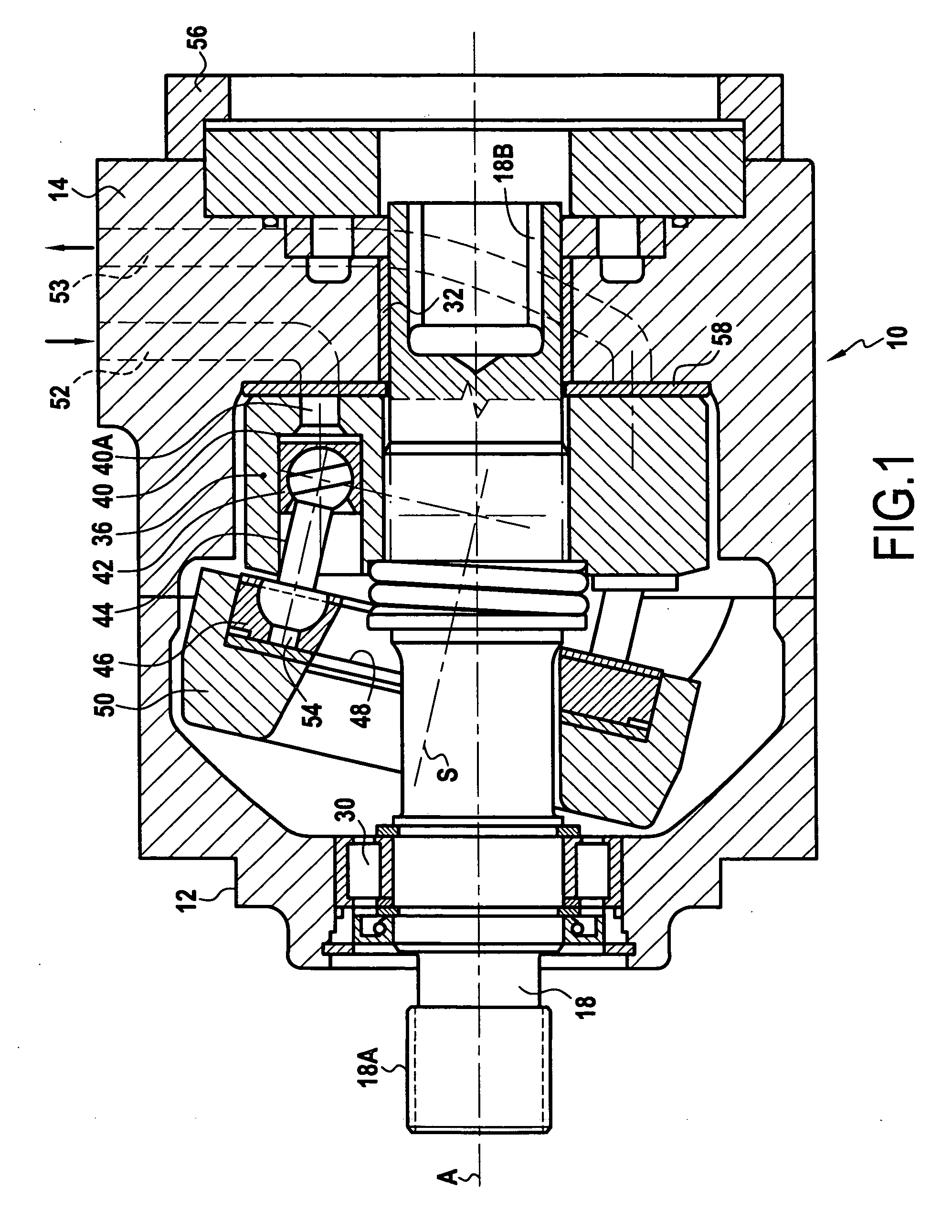
[0025]FIG. 1 shows a hydraulic machine in the form of a single axial piston pump unit indicated by the reference numeral 10. The housing structure of the pump unit 10 is formed by a first housing member 12 and a second housing member 14. The two housing members 12, 14 are connected together forming a central cavity therein. The two housing members 12, 14 encase a cylinder block 36 driven by a shaft 18, and a swash plate 50, so as to form a hydraulic unit such as a hydraulic pump.

[0026] The shaft 18 which is connectable to an internal combustion engine (not shown) or other such power source, is mounted inside the cavity formed by the connected first and second housing members 12, 14. A first end of the shaft 18 is mounted inside the first housing member 12 on a first bearing 30, and the second end of the shaft 18 is mounted inside the second housing 14 on a second bearing 32. In...


PUM


Abstract

A hydraulic machine (60, 70) comprising a housing (12, 14, 16) and at least first and second hydraulic units. Each unit comprising a cylinder block (36A, 36B) located in the housing and having pistons (42), and a shaft (18, 20) in rotational engagement with the cylinder block (36A, 36B). The shafts (18, 20) being arranged coaxially and being coupled so as to rotate together. The machine (60, 70) further comprising bearings (30, 32, 34, 71) for supporting the shafts (18, 20) in the housing (12, 14, 16). The shafts (18, 20) are coupled by corresponding male and female splined end portions (18A, 20A) thereof engaged one in the other, and the bearings (30, 32, 34, 71) comprise first and second bearings (30, 32) for respectively supporting the shafts (18, 20) at portions thereof located on the other sides of the cylinder blocks (36A, 36B) with respect to said splined end portions (18A, 20A). A single third bearing arrangement (34, 71) engages one of the shafts (18, 20) at least in the vicinity of the splined end portion (18A, 20A) thereof thereby supporting the shafts (18, 20) between said cylinder blocks (36A, 36B).

Description

FIELD OF THE INVENTION [0001] The present invention relates to a hydraulic machine. In particular, the present invention relates to a compact tandem axial piston pump unit with inclined swash plates. BACKGROUND OF THE INVENTION [0002] Known compact tandem pumps of axial piston configuration, with swash plates and coaxially arranged shafts are designed with the two ends of the pump housing being similar or identical to the front housing of a standard single pump. Between the two end portions of the housings a single or a double mid-housing is inserted in which an auxiliary pump can also be mounted. [0003] The shafts of both pumps and their corresponding cylinder blocks are supported by independent bearings. Accordingly, a bearing is arranged in each of the two end housings and two bearings are arranged in the mid-housing. Each shaft typically has a splined end in the mid housing area and both splined ends are in engagement with a separate splined hollow coupling member to permit torq...

Claims


Application Information

Patent Timeline
IPC IPC(8): F16D39/00
CPCF04B1/22F04B23/06F16D2001/103F16D31/02F16D1/02
Inventor GALBA, VLADIMIR
Owner SA POCLAIN HYDRAULICS B P
Learn More