Stereoscopic illumination endoscope system
a technology of endoscope and stereoscopic illumination, which is applied in the field of stereoscopic illumination endoscope system, can solve the problems of difficult to diagnose the extent of such asperities, difficult impractically complicated bundling of optical fibers, so as to facilitate stereoscopic view, maintain ease of detachment/attachment, and achieve the effect of avoiding the size of the light source uni
- Summary
- Abstract
- Description
- Claims
- Application Information
AI Technical Summary
Benefits of technology
Problems solved by technology
Method used
Image
Examples
embodiment 1
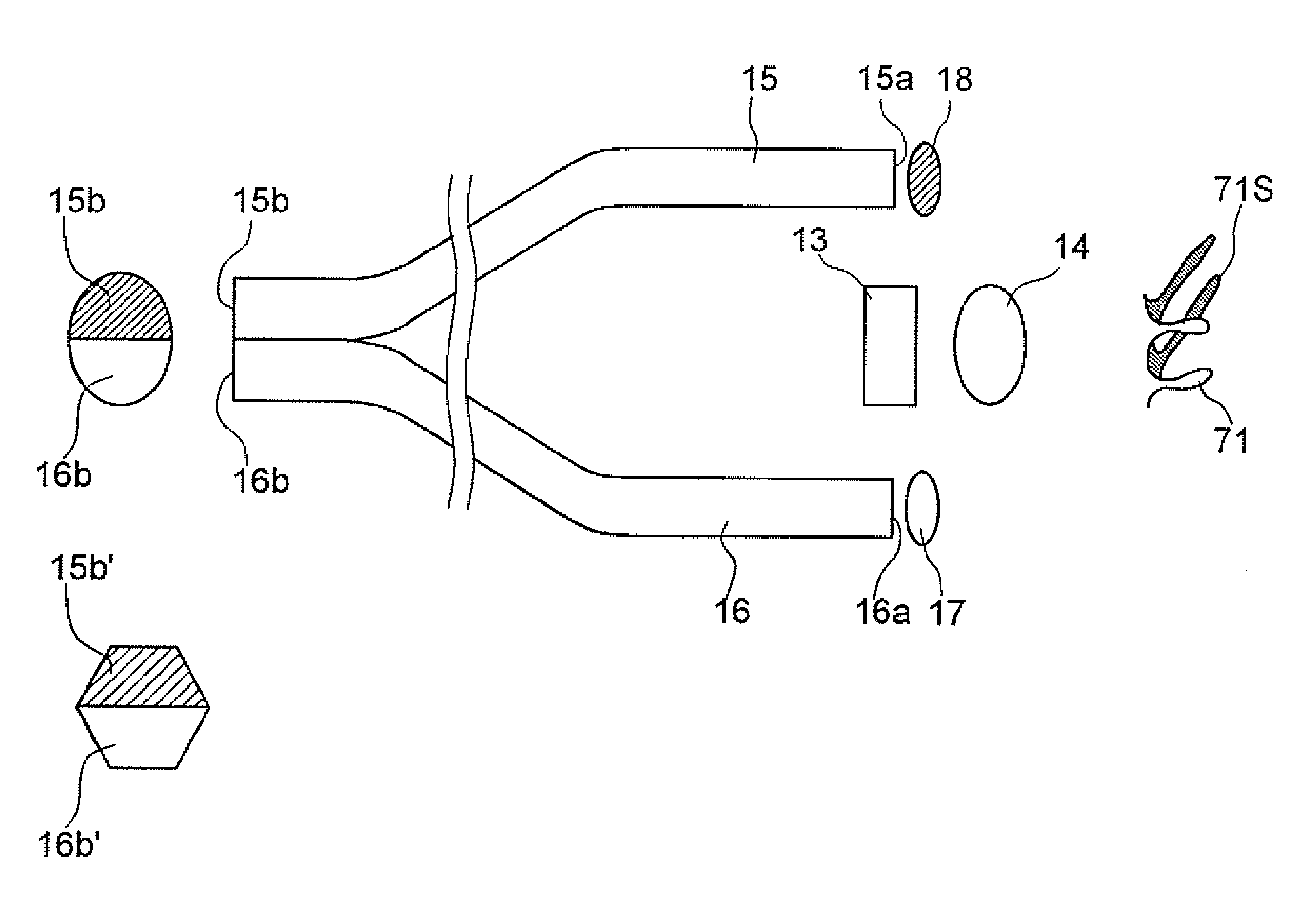
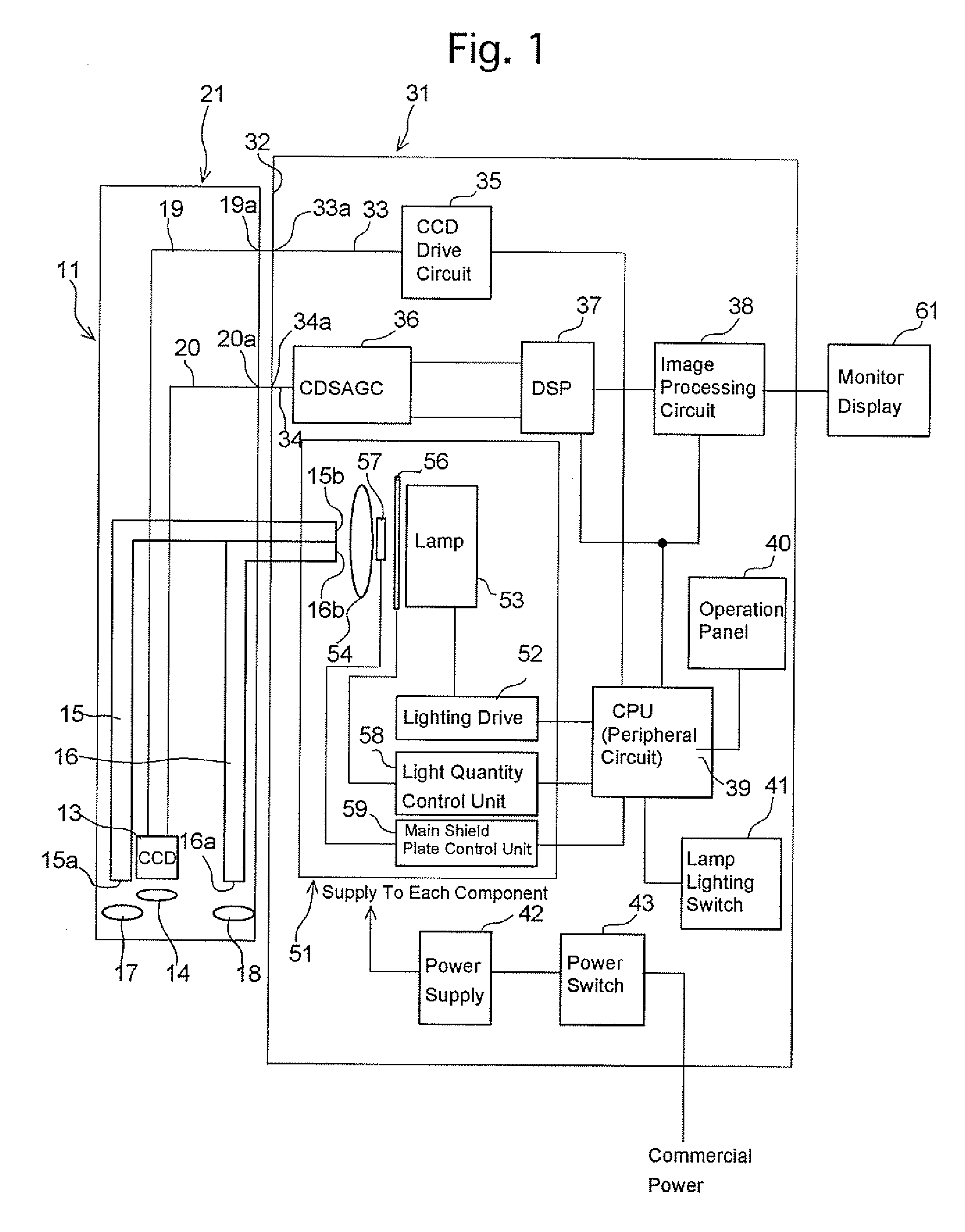
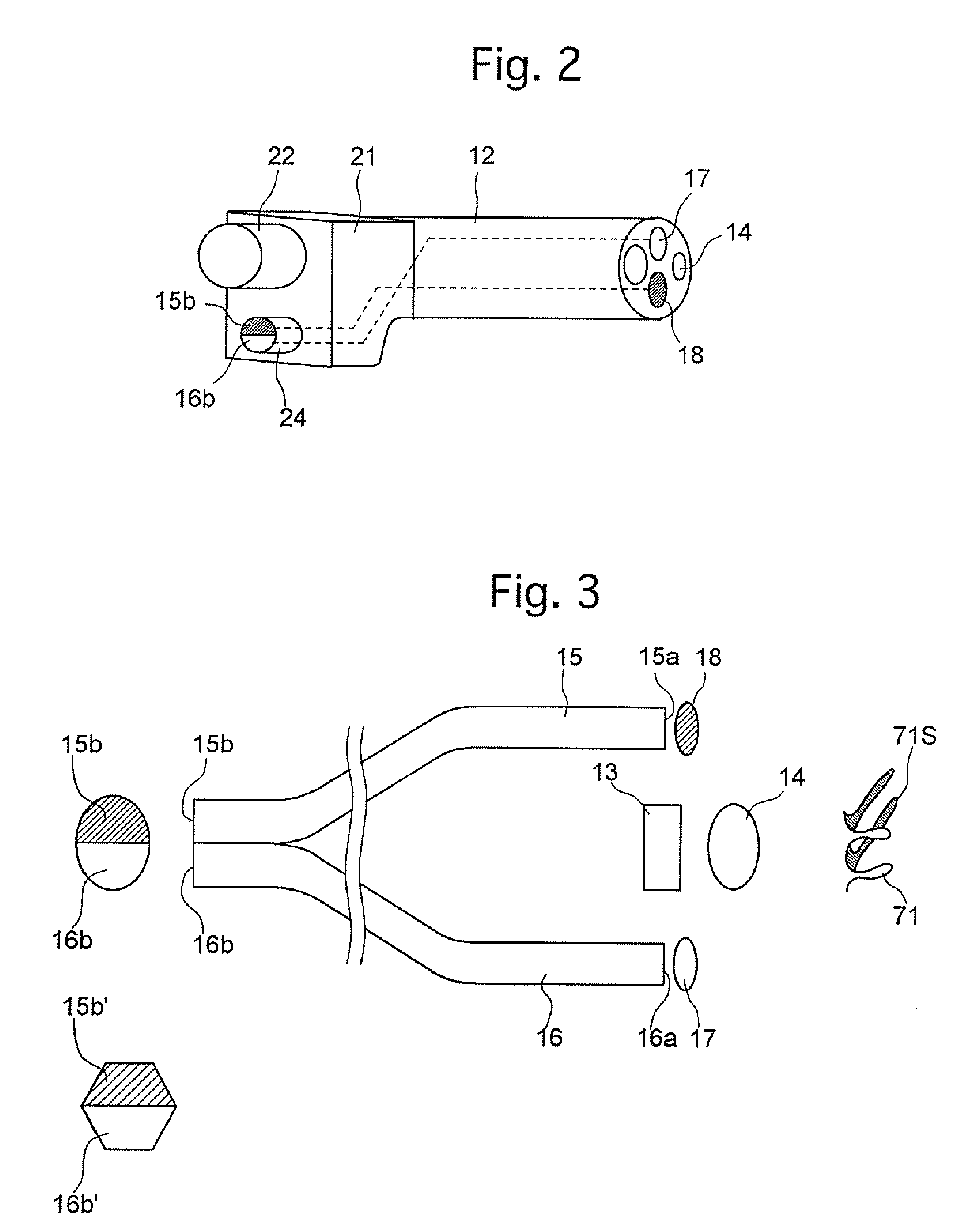
[0057]FIG. 4A shows the first embodiment of the present invention in which the light quantity control plate 56 is provided closer to the light source lamp 53, and the main shield plate 57 is provided closer to the incident-end faces 15b and 16b. The light quantity control plate 56 and main shield plate 57 provides differing quantities of light incident on the incident-end faces 15b and 16b, and also provides a light quantity control. In the first embodiment, a known xenon lamp having a built-in reflector is used as the light source lamp 53. The light source lamp 53 includes a reflector 531, an anode 532, and a cathode 533. The anode 532 protrudes inward from the apex of the reflector 531 along an optical axis O. The cathode 533 is arranged inside the reflector 531, with an end opposed to the end of the anode 532. The cathode 533 is supported by three metal plates 534 which extend toward the optical axis from the opening rim of the reflector 531. A heat-resistant transparent plate 53...
embodiment 2
[0064] The second embodiment according to the present invention will be described with reference to FIGS. 6A through 7. The first embodiment shown in FIGS. 4A to 5 has dealt with the case where the top shield plate 58a and the bottom shield plate 58b are arranged with a main shield plate (light shield) 571 therebetween, defining an upper aperture and a lower aperture; whereas in the second embodiment, an upper aperture 571a and a lower aperture 571b are formed in a main shield plate 571 instead. In the second embodiment, the light quantity control plate 56 and the main shield plate 571 are arranged between the light source lamp 53 and the condenser lens 54. The upper aperture 571a and the lower aperture 571b of the main shield plate 571 are substantially identical in area. FIGS. 6B and 7 shows illumination distributions of the upper and lower light bundles 53a and 53b incident on the incident-end faces 15b and 16b with the incident-end faces 15b and 16b positioned on the far side of...
embodiment 3
[0065]FIGS. 8A through 9 show the configuration of the third embodiment in which a main shield plate 572 is arranged between the condenser lens 54 and the incident-end faces 15b and 16b. In the third embodiment, since the main shield plate 572 is placed between the condenser lens 54 and the incident-end faces 15b and 16b, the light bundle passes through the main shield plate 572 with a smaller diameter due to the focusing of the condenser lens 54. Consequently, an upper aperture 572a and a lower aperture 572b of the main shield plate 572 can be formed smaller than the upper aperture 571a and the lower aperture 571b of the main shield plate 571 shown in FIGS. 6A through 7. This makes it possible to reduce the area of the main shield plate 572. In other respects, the configuration and function of the third embodiment are the same as the second embodiment.
PUM
 Abstract
Description
Claims
Application Information
 - R&D
- Intellectual Property
- Life Sciences
- Materials
- Tech Scout
- Unparalleled Data Quality
- Higher Quality Content
- 60% Fewer Hallucinations
Browse by: Latest US Patents, China's latest patents, Technical Efficacy Thesaurus, Application Domain, Technology Topic, Popular Technical Reports.
© 2025 PatSnap. All rights reserved.Legal|Privacy policy|Modern Slavery Act Transparency Statement|Sitemap|About US| Contact US: help@patsnap.com


