
Interface module with power over ethernet function

a technology of interface modules and functions, applied in frequency-division multiplexes, data switching networks, instruments, etc., can solve the problems of increasing the overall cost of such systems, increasing the cost of power delivery to individual field devices, and increasing the complexity of installation time,

Active Publication Date: 2007-01-25
ROSEMOUNT INC
View PDF99 Cites 103 Cited by
  • Summary
  • Abstract
  • Description
  • Claims
  • Application Information

AI Technical Summary

Benefits of technology

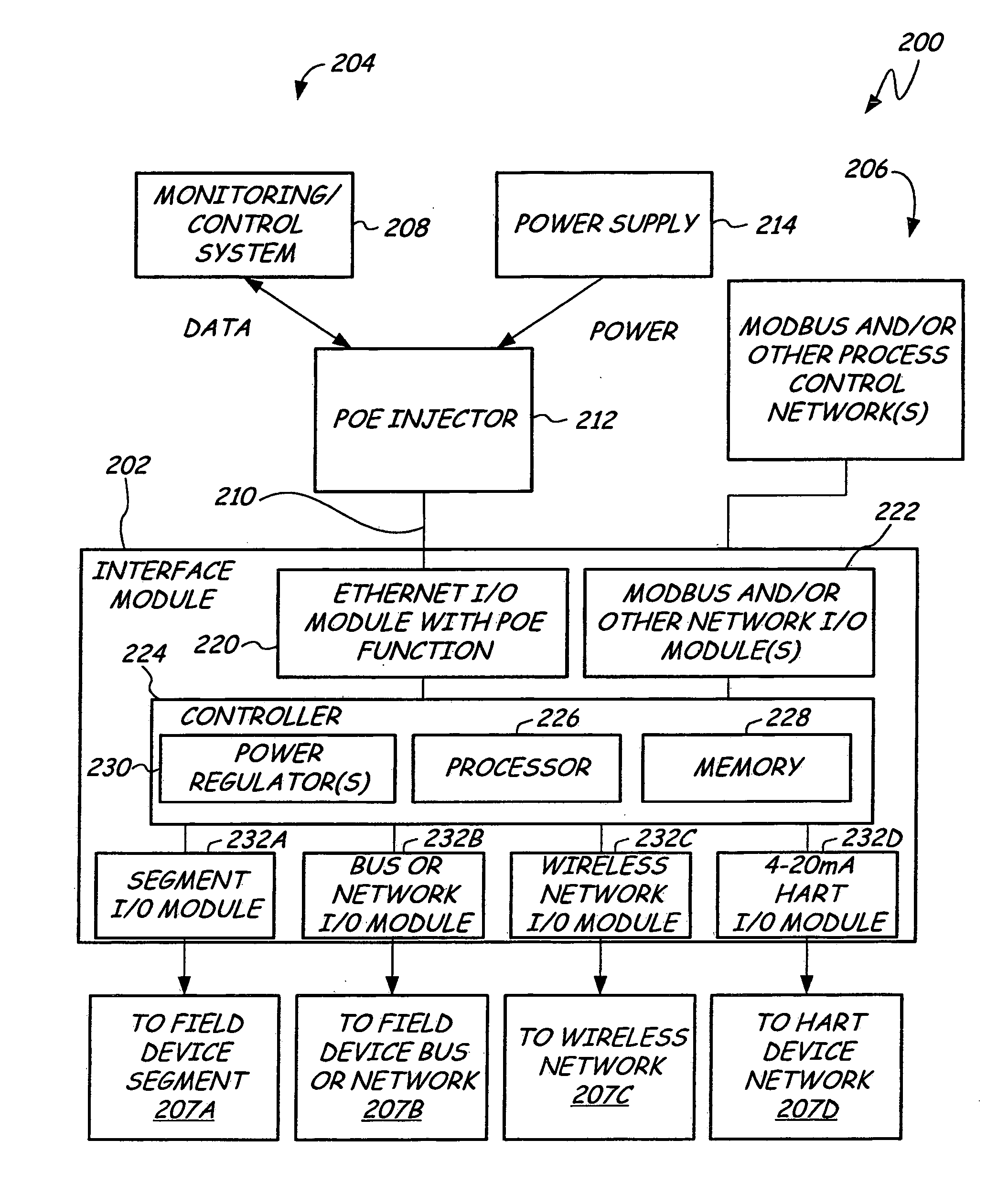
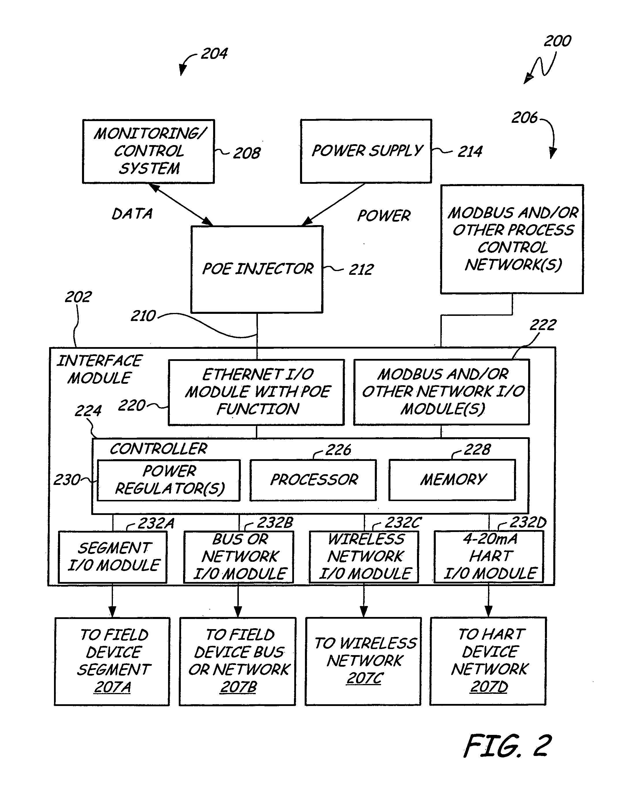
[0009] An interface module for use in a process control or monitoring system has an Ethernet port, a controller, and at least one segment I / O module. The Ethernet port is adapted to send and receive signals in an Ethernet protocol over a cable comprising a plurality of wires and to receive a voltage potential from at least one pair of the plurality of wires. The controller is coupled to the Ethernet port and powered from the received voltage potential. The at least one segment I / O module is coupled to the controller and is adapted to couple to an associated field device segment with at least one attached field device. The at least one segment I / O module is adapted to interact with the at least one attached field device on the associated field device segment.

Problems solved by technology

Regardless of the communications protocol used, power delivery to individual field devices and to interface modules and junctions within process monitoring and control networks impose costs.
In particular, cabling itself and the cost of cable installation increase the overall costs of such systems.
Moreover, when adding new devices to network, stringing additional cables to deliver power and signals to the new devices adds to the costs, complexity, and installation time.

Method used


Image

  • Interface module with power over ethernet function
  • Interface module with power over ethernet function
  • Interface module with power over ethernet function

Examples


Embodiment Construction

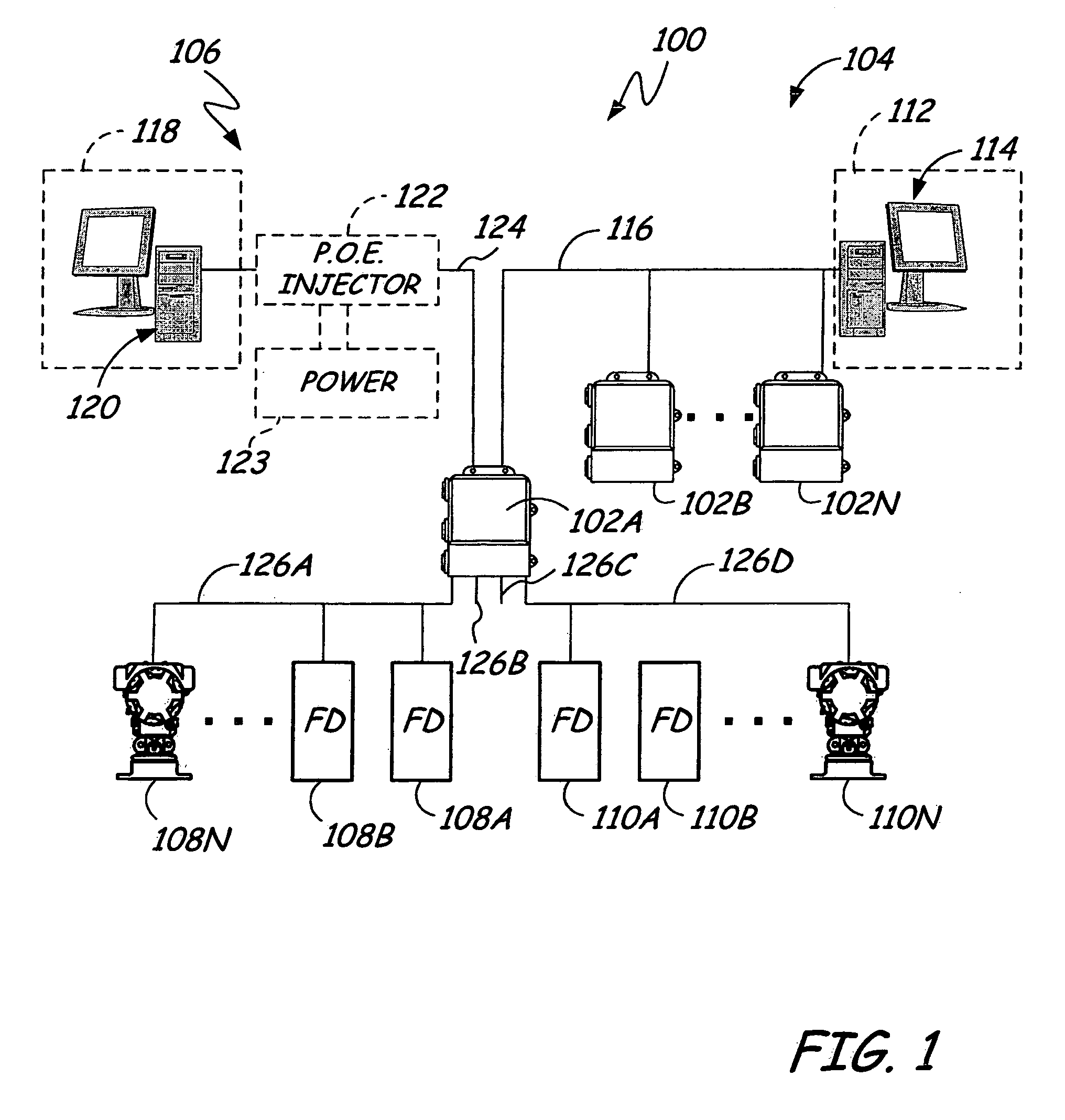
[0014]FIG. 1 illustrates a simplified block diagram of a process control or monitoring system 100 having an interface module 102A adapted to couple one or more networks 104 and 106 to a plurality of field devices 108A-110N, where any number of field devices can be used.

[0015] Network 104 is comprised of a system 112 with an operator interface 114 (such as a workstation or computer), which can be coupled to the one or more interface modules 102A-102N via cabling 116. Communications between the system 112 and the interface modules 102A-102N can be in any communication protocol, including, for example, MODBUS, PROFIBUS®, AS-Interface, WORLDFIP®, Device-Net®, CAN, and FIELDBUS protocols.

[0016] Process network 106 is comprised of a control or monitoring system 118 with an operator interface 120 (such as a user workstation or computer), which can be coupled through a Power over Ethernet injector (POE injector) 122 via Ethernet cabling 124 to one or more of the interface modules 102A-102...


PUM


Abstract

An interface module for use in a process monitoring and control system has an Ethernet port, a controller, and at least one segment I / O module. The Ethernet port is adapted to send and receive signals in an Ethernet protocol over a cable comprising a plurality of wires and to receive a voltage potential from at least one pair of the plurality of wires. The controller is coupled to the Ethernet port and powered from the received voltage potential. The at least one segment I / O module is coupled to the controller and is adapted to couple to an associated field device segment with at least one attached field device. The at least one segment I / O module is adapted to interact with the at least one attached field device on the associated field device segment.

Description

FIELD OF INVENTION [0001] The present disclosure relates generally to process monitoring and / or control systems, and more particularly, to process control systems and process monitoring systems adapted for Ethernet-based power distribution. BACKGROUND OF THE INVENTION [0002] Process monitoring and control systems, such as those used in chemical processes, petroleum, or other types of industrial processes, typically include a centralized monitoring and control system communicatively coupled to a workstation of an operator or user and to one or more field devices via analog or digital communication paths. Field devices can be sensors adapted to monitor process parameters (such as temperature, pressure, flow rate, and the like) and / or transducers adapted to perform operations on the industrial process (such as opening and closing valves, and so on). [0003] Generally, the centralized monitoring and control system receives signals indicative of process measurements made by the field devi...

Claims


Application Information

Patent Timeline
IPC IPC(8): G06F15/173H04J1/16
CPCH04L12/10
Inventor BREWER, JOHN PAULROTVOLD, ERIC DARRELLORTH, KELLY MICHAELKARSCHNIA, ROBERT JOHNOSTBY, PHILIP GORDONLATTIMER, DONALD ROBERT
Owner ROSEMOUNT INC
Learn More