
Battery device of vehicle power supply

a battery and power supply technology, applied in the direction of vehicle components, electric/fluid circuits, transportation and packaging, etc., can solve the problems of noise damage to electronic components and batteries, increased manufacturing costs, and high labor costs, so as to prevent the metal screw from being loosened, simple structure, and effective prevention of the effect of loosening

Inactive Publication Date: 2007-01-25
SANYO ELECTRIC CO LTD
View PDF14 Cites 19 Cited by
  • Summary
  • Abstract
  • Description
  • Claims
  • Application Information

AI Technical Summary

Benefits of technology

[0008] The present invention has been developed in order to solve the aforementioned drawbacks. An important object of the present invention is to provide a power device for a vehicle which can effectively prevent a fastening portion from being loosened due to a change in a temperature and can firmly fix a resin component to a base portion with a very simple structure.
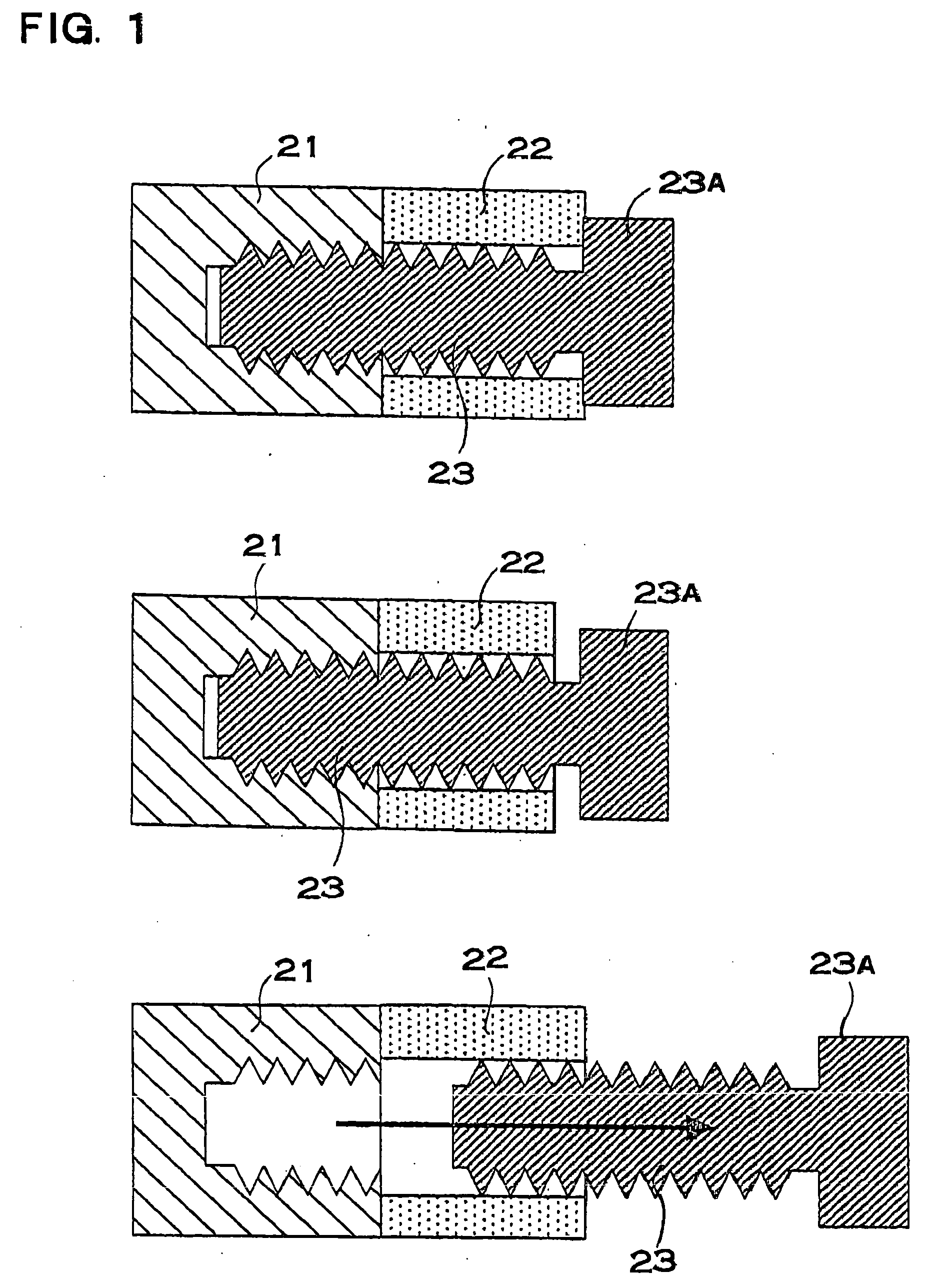
[0010] The power device described above has such a feature that the metal screw can be effectively prevented from being loosened due to a change in a temperature and the resin component can be firmly fixed to the base portion with a very simple structure. The reason is that the metal sleeve having the flange is inserted in the through hole of the resin component and the metal screw is inserted through the metal sleeve to hold the metal sleeve, thereby fixing the resin component to the base portion. The thermal expansion of a metal is smaller than that of a synthetic resin, and the thermal expansion of the metal sleeve is smaller than that of the resin component. For this reason, the amount of deformation caused by a change in the temperature of the metal sleeve is smaller than that of the resin component. Even if the resin component repeats a thermal expansion and a thermal contraction due to the change in the temperature, the thermal expansion of the metal sleeve is small and the metal sleeve is firmly held and fixed between the metal screw and the base portion. According to the present invention, therefore, it is possible to effectively prevent the metal screw from being loosened due to a change in a temperature and to firmly fix the resin component to the base portion.
[0011] Furthermore, the power device described above is provided with the flange on the opposed surface to the base portion of the metal sleeve, and the resin component is fixed to the base portion with the metal screw in a state in which the flange is caused to abut on the support member of the base portion. The flange of the metal sleeve comes in contact with the support member in a large area. For this reason, the support member presses, holds and fixes the metal sleeve at a uniform pressure. Therefore, the metal sleeve is held by the support member so that an imbalanced pressing force does not locally act thereon, and the metal sleeve can be prevented from taking an unnatural posture, the position of the metal sleeve can be prevented from being shifted, and the metal sleeve and the resin component can be interposed between the support member and the metal screw in an ideal condition and can be thus fixed to the base portion.

Problems solved by technology

For this reason, a manufacturing cost is increased more greatly as compared with an ordinary screw or nut.
Therefore, there is also a drawback that a great deal of time and labor is required for fastening and removal.
The clearance causes a vibration or a noise to damage an electronic component and a battery, and furthermore, an uncomfortable noise is made in the automobile.

Method used


Image

  • Battery device of vehicle power supply
  • Battery device of vehicle power supply
  • Battery device of vehicle power supply

Examples


Embodiment Construction

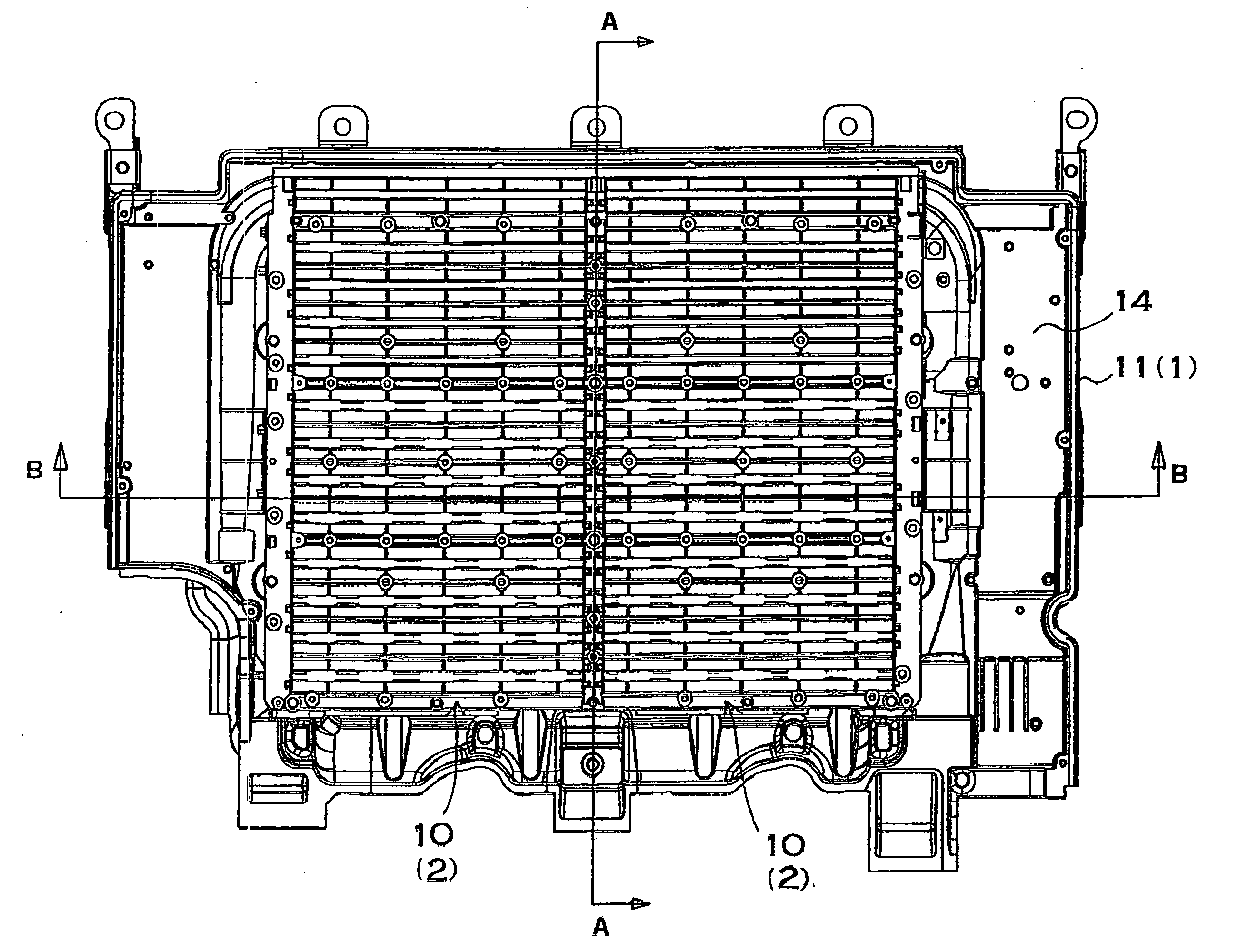
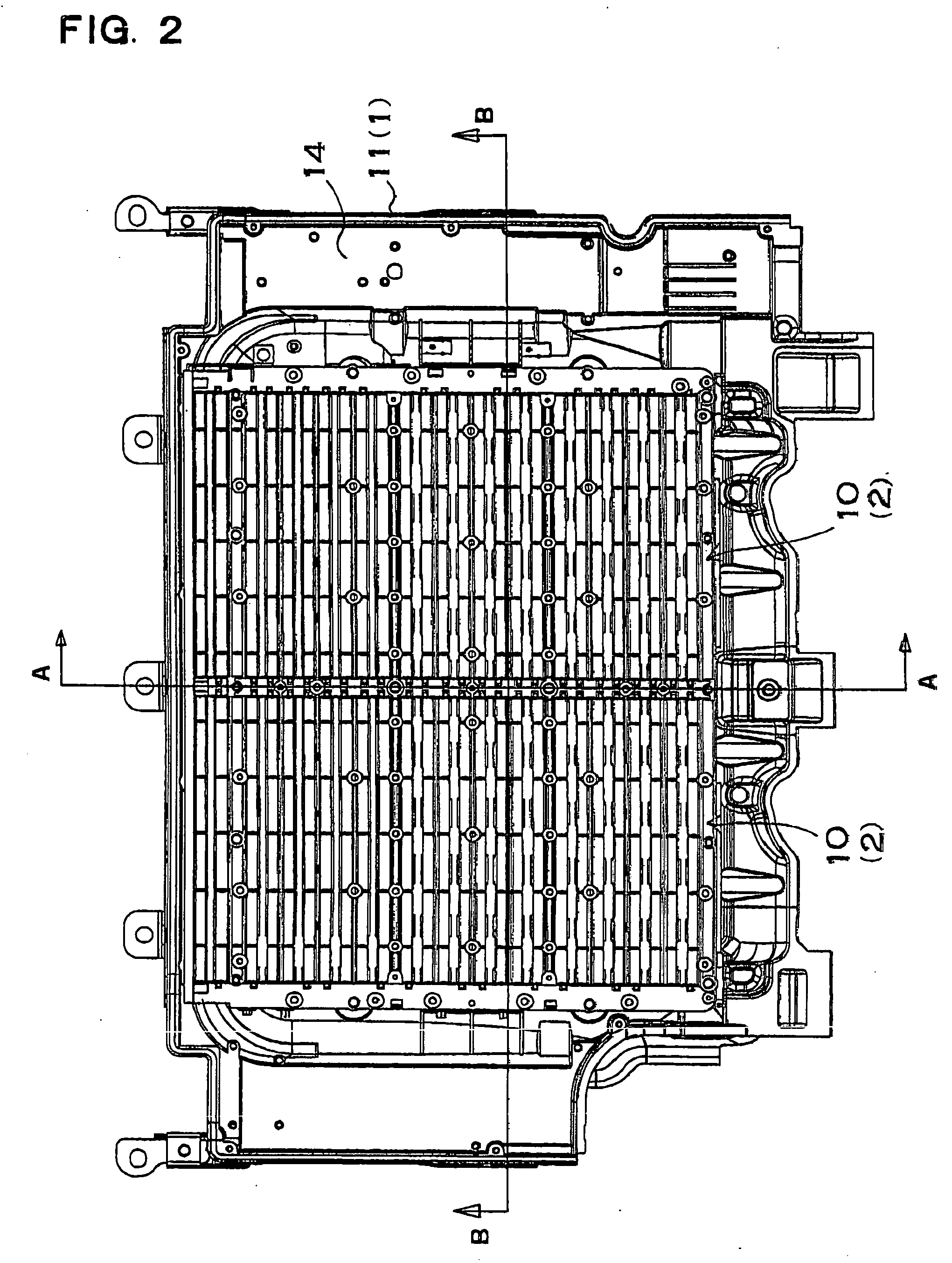
[0027] In a power device for a vehicle shown in FIGS. 2 to 7, a resin component 2 to be a holder case 10 is fixed onto a base portion 1 with a metal screw 3. The resin component 2 shown in the drawings is the holder case 10 formed of plastic which accommodates a plurality of battery modules therein (not shown). In the power device shown in the drawings, the holder case 10 is laminated as the resin component 2 in two stages and is fixed to the base portion 1. Each holder case 10 has an upper case 10A and a lower case 10B which interpose and hold the battery module from above and below. Accordingly, the resin component 2 is the holder case 10 laminated by a division into four portions. Each holder case 10 is integrally formed of plastic. The holder case 10 to be the resin component 2 is plastic reinforced by embedding a reinforcing fiber such as a glass fiber. The resin component can be formed of plastic which does not embed the reinforcing fiber. Moreover, the resin component is a th...


PUM


Abstract

A power device for a vehicle includes a base portion to be mounted on the vehicle, a resin component having a through hole which is to be fixed to the base portion, a metal sleeve inserted through an internal surface of the through hole of the resin component and having a flange on an opposed surface to the base portion, and a metal screw inserted through the metal sleeve inserted in the through hole of the resin component, thereby fixing the resin component to the base portion through the metal sleeve. The base portion has a female screw member into which a tip portion of the metal screw is to be screwed and has a support member provided on an opposed surface to the metal sleeve. In the power device, the metal screw is inserted through the metal sleeve to screw a screw portion on a tip into the female screw member and fixes the metal sleeve to the base portion, thereby securing the resin component to the base portion.

Description

BACKGROUND OF THE INVENTION [0001] 1. Field of the Invention [0002] The present invention relates to a power device to be mounted on a vehicle such as an automobile, and more particularly to a power device in which a resin component is fixed to a base portion with a screw so as not to be loosened. [0003] 2. Description of the Related Art [0004] A power device to be mounted on an automobile has a built-in battery for driving a motor to cause the automobile to run. The power device is fixed to a vehicle with a screw and a nut to be removable and attachable in order to maintain the built-in battery and electronic equipment. The power device can be decomposed by removing the screw when the maintenance is to be carried out. When the battery breaks down, particularly, the battery is to be exchanged. For this reason, it is necessary to employ a structure in which a holder case accommodating the batter can be decomposed. Moreover, the power device to be mounted on the vehicle is to have a w...

Claims


Application Information

Patent Timeline
Patent Type & Authority Applications(United States)
IPC IPC(8): B60R16/04
CPCB60R16/04
Inventor FUJII, KAZUHIROIZAWA, RYOSAKUAOISHI, KOICHI
Owner SANYO ELECTRIC CO LTD
Learn More