Virtual Cells for Wireless Networks
a wireless network and virtual cell technology, applied in the field of virtual cell for wireless networks, can solve the problems of reducing the cell size to the point where the handoff sequence may be too burdensome to implement, and the natural limits of the bandwidth and coverage that users can offer,
- Summary
- Abstract
- Description
- Claims
- Application Information
AI Technical Summary
Benefits of technology
Problems solved by technology
Method used
Image
Examples
embodiment 100
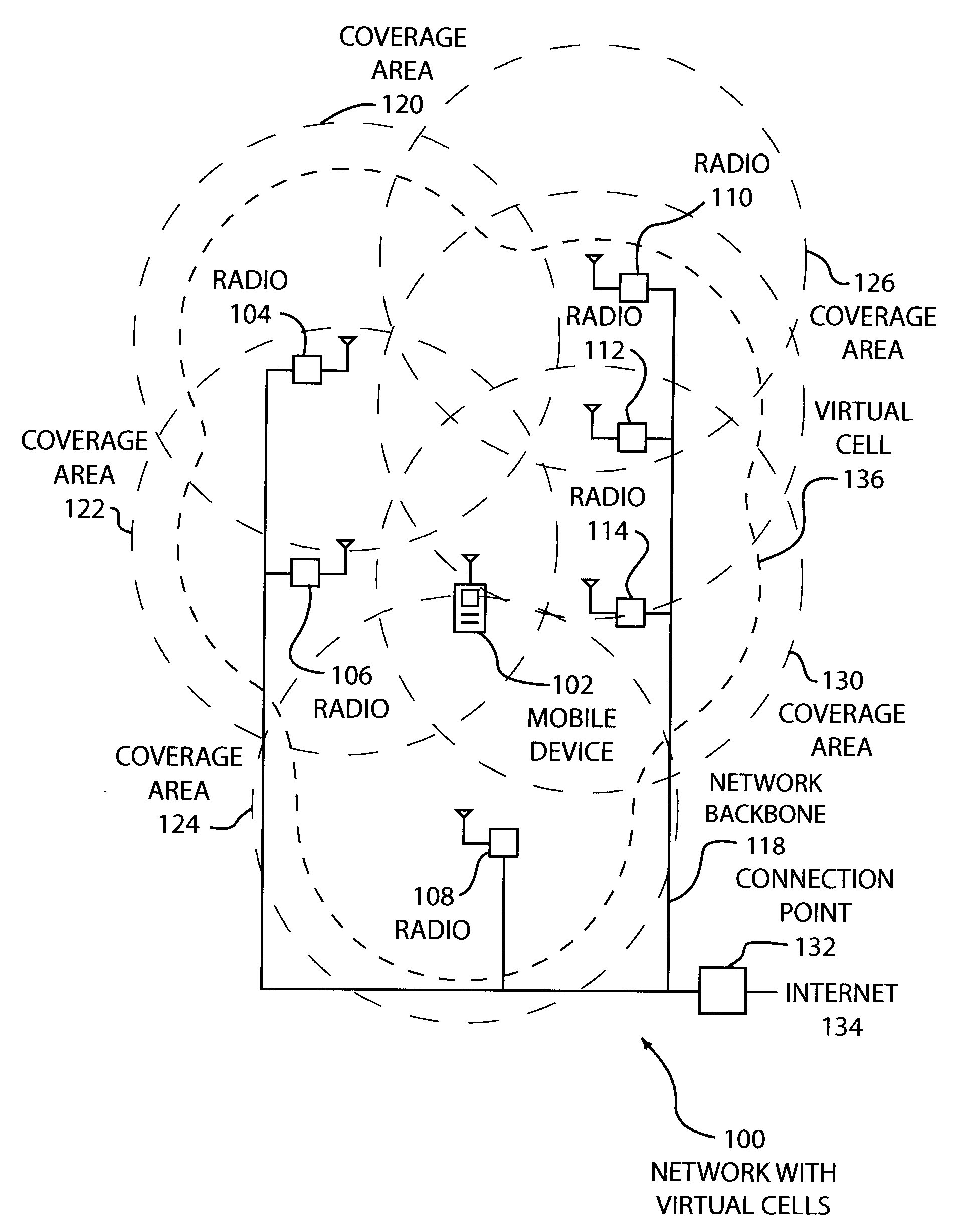
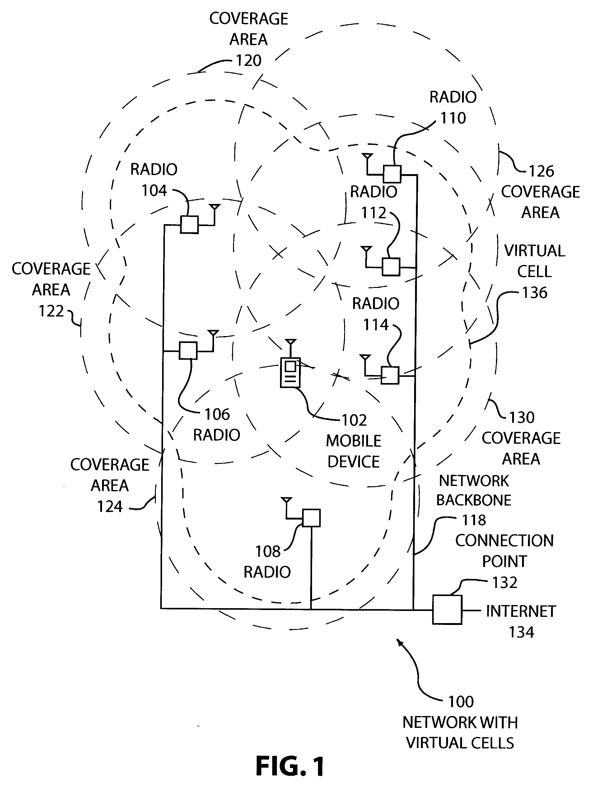
[0023]FIG. 1 illustrates an embodiment 100 showing a wireless network having virtual cells. A mobile device 102 can communicate with any radio 104, 106, 108, 110, 112, and 114 of the network. The radios are connected by an network backbone 118. Each of the radios 104, 106, 108, 110, 112, and 114 has a coverage area 120, 122, 124, 126, 128, and 130, respectively. The network backbone 118 has a connection point 132 that may be connected to the internet 134 or another network.
[0024] When the mobile device 102 is in communication with the network, a ‘virtual cell’136 comprising the radios 104, 106, 108, 112, and 114 may be created. The virtual cell may allow the mobile device 102 to move anywhere within the virtual cell and keep in regular communication with the network.
[0025] The network of radios may be any type of wireless network, such as cellular telephones, wi-fi hotspots, 802.11 networks, or any other network where a backbone has several radio transmitters capable of communicati...
embodiment 200
[0035]FIG. 2 illustrates an embodiment 200 showing the selection of virtual cells using movement vectors. A mobile device is shown at a first position 202 with movement vector 204. The mobile device is also shown at a second position 206 with a second movement vector 208. The mobile device is shown following a highway 210.
[0036] From the first position 202 with movement vector 204, a virtual cell 228 may be created from coverage areas 214, 216, 218, and 220. At the second position 206, a virtual cell 230 may comprise coverage areas 218, 220, 222, 224, and 226.
[0037] The embodiment 200 illustrates how some virtual cells may be selected based on the movement of a mobile device within the network. As the mobile device moves along the highway 210, the position and movement vector may be determined by communicating with the device in coverage area 212 and then coverage area 214 in succession. From the two communication sessions, the movement vector 204 may be determined.
[0038] In some ...
embodiment 300
[0051]FIG. 3 is a timeline illustration of an embodiment 300 for communicating between a mobile device and a network with virtual cells. Actions of a mobile device are in the center column 302. Actions of a first transceiver are in the left column 304, and actions of a second transceiver are in the right column 306.
[0052] The mobile device establishes communications with the network in block 308 by communicating with the first transceiver that receives the request in block 310. After determining that a virtual cell is appropriate in block 312, the virtual cell is established in block 314 by the first transceiver and in block 316 by the second transceiver. An outgoing communications packet is sent to all virtual cell members in block 318 and received by the second transceiver in block 320. In blocks 322 and 324, both transceivers synchronously transmit the communications packet, which is received by the mobile device in block 326.
[0053] The mobile device transmits a packet in block ...
PUM
 Abstract
Description
Claims
Application Information
 - R&D
- Intellectual Property
- Life Sciences
- Materials
- Tech Scout
- Unparalleled Data Quality
- Higher Quality Content
- 60% Fewer Hallucinations
Browse by: Latest US Patents, China's latest patents, Technical Efficacy Thesaurus, Application Domain, Technology Topic, Popular Technical Reports.
© 2025 PatSnap. All rights reserved.Legal|Privacy policy|Modern Slavery Act Transparency Statement|Sitemap|About US| Contact US: help@patsnap.com


