Eureka AIR delivers breakthrough ideas for toughest innovation challenges, trusted by R&D personnel around the world.

Flexible micro-electro-mechanical transducer

Active Publication Date: 2007-01-18
KOLO MEDICAL (SUZHOU) CO LTD
View PDF10 Cites 87 Cited by
  • Summary
  • Abstract
  • Description
  • Claims
  • Application Information

AI Technical Summary

Benefits of technology

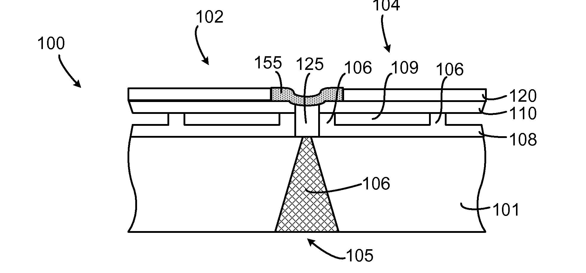
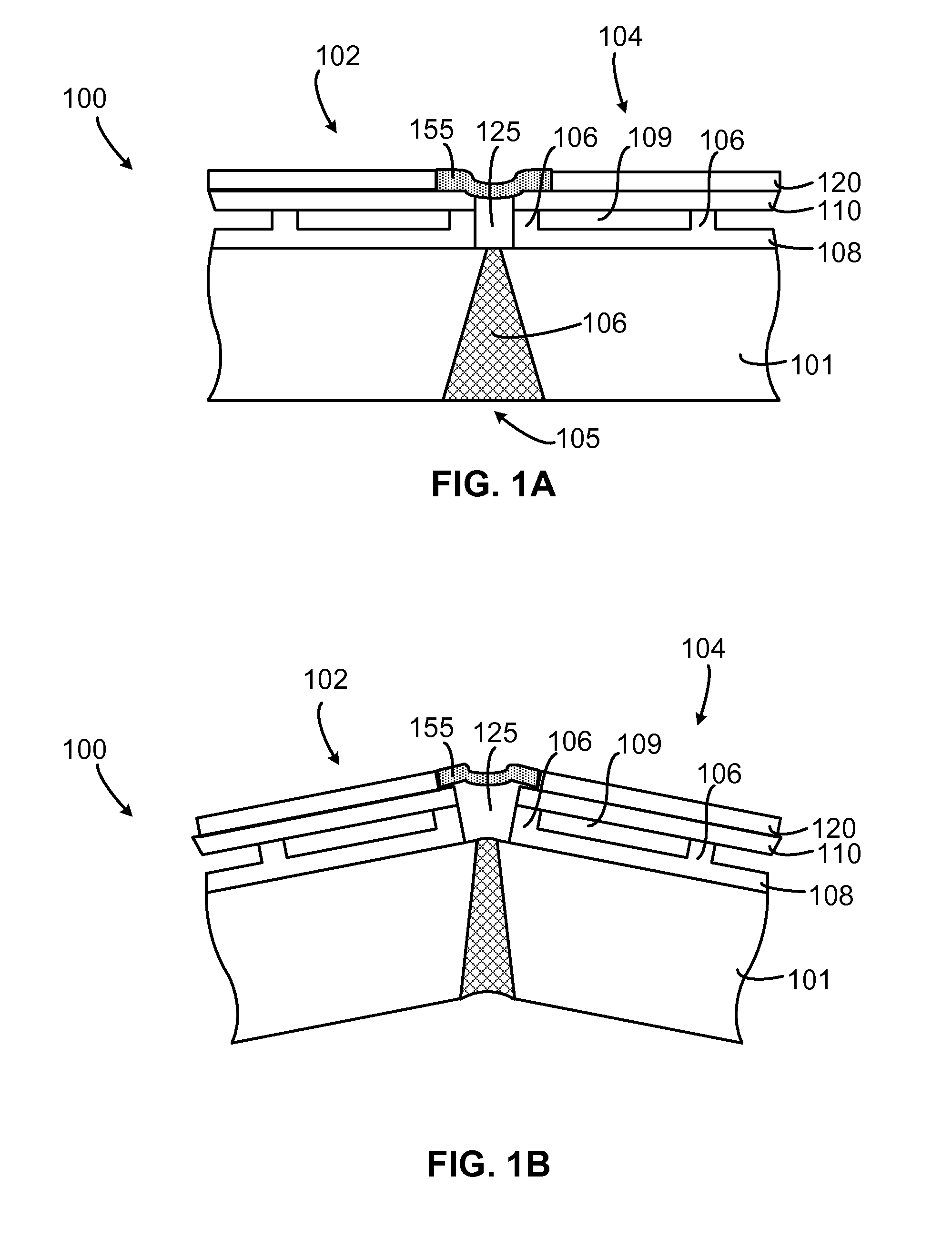
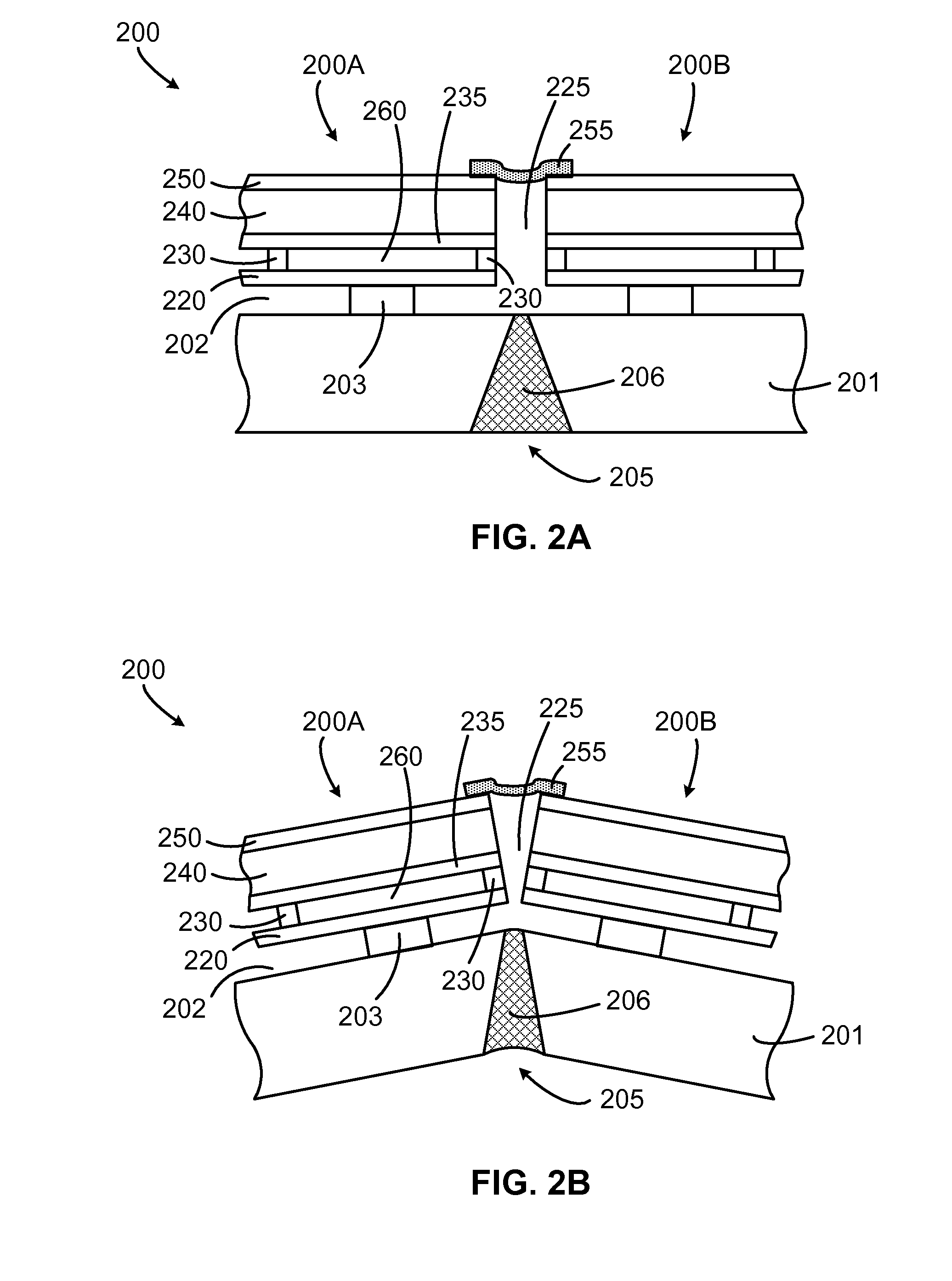
[0021] Furthermore, trench openings between the surface portions of neighboring transducer elements may be formed to facilitate angling of the transducer elements during bending of the substrate. The trench openings also accurately define the separation between the elements (and thus the size of the transducer elements) to make the fabrication process easier. The trench openings may be filled with a desired filler material.
[0024] According to another aspect of the present invention, a method for making a flexible or bent micro-electro-mechanical transducer is disclosed. The method has two main steps: (1) fabricating a plurality of transducer elements on a substrate, each transducer element having a surface portion including a movable transducing member, the surface portion being spaced from the substrate to define a transducing gap between the movable transducing member and the substrate; (2) cutting a slot through a bottom surface of the substrate; and (3) filling the slot using a flexible material. The soft filler material provides support to the structure of the transducer during the fabrication process and maintains the integrity of the device after fabrication. The slot is preferably cut at a position between two neighboring transducer elements to allow bending of the substrate and angling of the surface portions of the neighboring transducer elements. The slot preferably has a shape with nonuniform cross-sectional sizes which generally increase from the top of the substrate to the bottom facing away the transducer elements.

Problems solved by technology

This process is fraught with difficulties and high expenses, not to mention the large input impedance mismatch problem presented by such elements to transmit / receiving electronics.
The present curved cMUTs are difficult and expensive to fabricate due to lack of controllability and insufficient maneuverability.
Furthermore, once fabricated the curved cMUTs have a fixed curvature that cannot be changed or controlled.

Method used


Image

  • Flexible micro-electro-mechanical transducer
  • Flexible micro-electro-mechanical transducer
  • Flexible micro-electro-mechanical transducer

Examples


Embodiment Construction

[0050] The micro-electro-mechanical transducer such as a capacitance micromachined ultrasonic transducer (cMUT) of the present invention will be described in detail along with the figures, in which like parts are denoted with like reference numerals or letters. The micro-electro-mechanical transducer may be fabricated using any suitable methods, particularly using the methods disclosed herein and in the several patent applications identified herein.

[0051] The invention has been described below with reference to specific embodiments. In most cases, a cMUT structure is used to illustrate the invention. It is appreciated, however, that the present invention is not limited to cMUTs. It will be apparent to those skilled in the art that various modifications may be made and other embodiments can be used without departing from the broader scope of the inventions. Therefore, these and other variations upon the specific embodiments are intended to be covered by the present inventions. Those...


PUM

PropertyMeasurementUnit
Temperatureaaaaaaaaaa
Thicknessaaaaaaaaaa
Flexibilityaaaaaaaaaa

Abstract

A curved or bendable micro-electro-mechanical transducer (such as the cMUT) is disclosed. The transducer has a plurality of transducer elements built on a substrate. The substrate has a slot below every two neighboring device elements. Each slot is at least at least partially filled with a flexible material to allow bending of the substrate. A bending actuator may be included to facilitate the bending of the substrate. An exemplary bending actuator uses a nonuniformly shrinkable material to bend the substrate. A curved or bendable cMUT of the present invention can be configured to be an intravascular ultrasound (IVUS) device.

Description

CROSS-REFERENCE TO RELATED APPLICATIONS [0001] This application claims priority from U.S. Provisional Applications Ser. No. 60 / 692,038, filed Jun. 17, 2005; Ser. No. 60 / 705,606, filed Aug. 3, 2005; and Ser. No. 60 / 744242, filed Apr. 4, 2006, which applications are incorporated herein by reference in their entirety. [0002] This application further incorporates herein by reference in entirety the following: [0003] International Application (PCT) No. PCT / IB2006 / 051566, entitled THROUGH WAFER INTERCONNECTION, filed on May 18, 2006; [0004] International Application (PCT) No. PCT / IB2006 / 051567, entitled METHODS FOR FABRICATING MICRO-ELECTRO-MECHANICAL DEVICES, filed on May 18, 2006; [0005] International Application (PCT) No. PCT / IB2006 / 051568, entitled MICRO-ELECTRO-MECHANICAL TRANSDUCERS, filed on May 18, 2006; [0006] International Application (PCT) No. PCT / IB2006 / 051569, entitled MICRO-ELECTRO-MECHANICAL TRANSDUCERS, filed on May 18, 2006; and [0007] International Application (PCT) No. ...

Claims


Application Information

Patent Timeline
IPC IPC(8): H01L41/00
CPCB06B1/0292B81B3/0021G01N29/2406Y10T29/49005H01L2924/0002H01L41/0973H01L2924/00H10N30/2047H02N1/006
Inventor HUANG, YONGLI
Owner KOLO MEDICAL (SUZHOU) CO LTD
Why Eureka
Eureka Blog
Learn More