In-vehicle electronic control device

a technology of electronic control device and vehicle, which is applied in the direction of electric vehicles, vehicle components, electric devices, etc., can solve the problem of not making reference to a method of writing output voltage correction data in the data memory, and achieve the effect of simplifying dispatch adjustment equipment and avoiding an increase in control burden shar

Inactive Publication Date: 2007-01-18
MITSUBISHI ELECTRIC CORP
View PDF5 Cites 26 Cited by
  • Summary
  • Abstract
  • Description
  • Claims
  • Application Information

AI Technical Summary

Benefits of technology

The invention provides an in-vehicle electronic control device with a constant voltage power source circuit that ensures high accuracy output voltage in conjunction with a simple product inspection equipment. The device also prevents degradation in reliability with respect to an abnormality in circuit component added for improving output voltage accuracy. The device includes a microprocessor with nonvolatile program memory, a first nonvolatile data memory, and an arithmetic processing RAM memory. The constant voltage power source circuit generates a predetermined constant voltage output voltage using power controlled and supplied by an in-vehicle battery via a power transistor. The output voltage adjustment circuit includes a reference voltage generation circuit, a comparison amplification circuit, and a resistance circuit network for fine adjustment of the comparison input voltages and negative feedback control on the output voltage. The multi-channel AD converter generates a maximum digital output of a predetermined resolving power when the analog input voltage is equal to the reference voltage. The correction data calculating and transferring unit operates when a deviation voltage between the external measurement voltage and the target value is excessive to calculate output voltage correction data in the nonvolatile second data memory. The proofread confirmation unit reads the external measurement voltage and stores it in the in-vehicle electronic control device to confirm whether the deviation is corrected to an allowable error range. The correction data is retained even in the case of interruption of the battery connection, avoiding the need for an external equipment and increasing control burden on the microprocessor.

Problems solved by technology

However, no reference is made to a method of writing output voltage correction data in the data memory.
Also, since an abnormality in the constant voltage power source circuit involves the risk of damaging other circuit components, it is necessary to take all possible measures to avoid reliability to be degraded by adding a circuit component even when the addition of component contributes to improvements in constant voltage control accuracy.

Method used


Image

  • In-vehicle electronic control device
  • In-vehicle electronic control device
  • In-vehicle electronic control device

Examples


first embodiment

(1) Detailed Description of First Embodiment

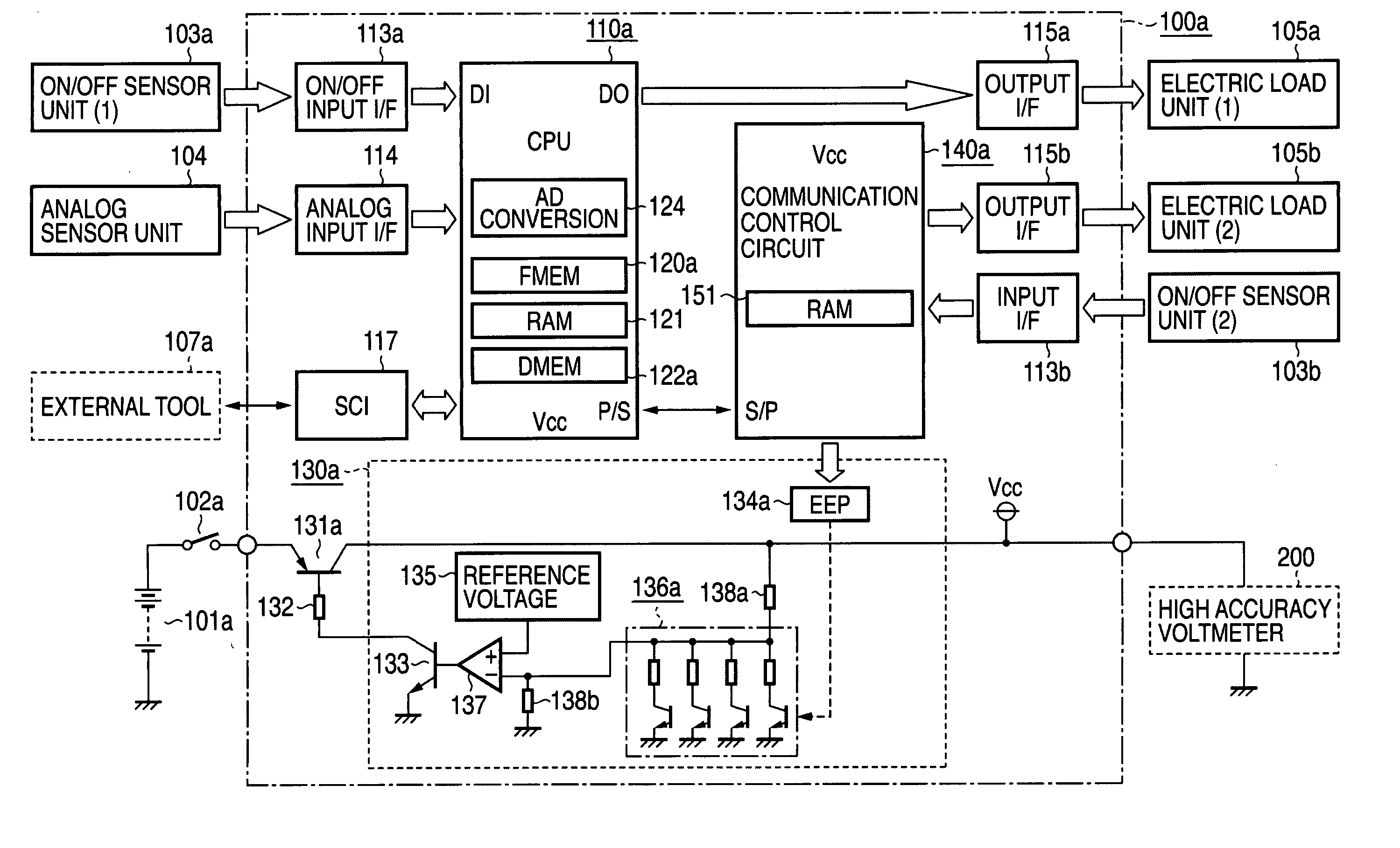
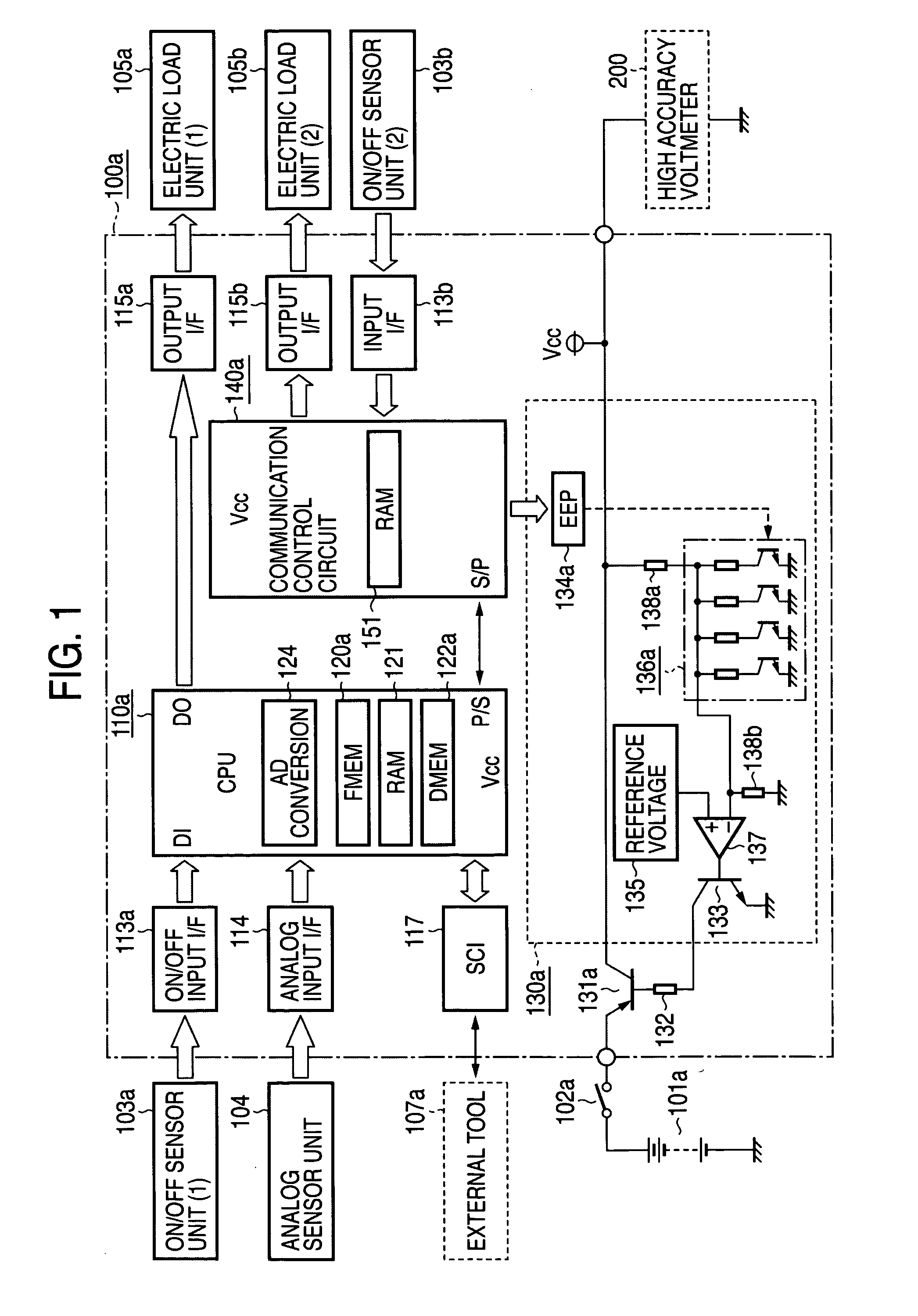
[0032] Hereinafter, description will be given with reference to FIG. 1 of a block diagram showing an in-vehicle electronic control device as a whole according to a first embodiment of this invention.

[0033] Referring to FIG. 1, an in-vehicle electronic control device 100a is mounted on an electronic substrate housed in a closed housing (not shown) and connected to an external input / output unit described later in this specification via a detachable connector (not shown).

[0034] An in-vehicle battery 101a generates a direct current voltage of 12 V, for example, to supply power to the in-vehicle electronic device 100a via a power switch 102a such as a key switch and the like.

[0035] An on / off sensor unit 103a is an on / off switch unit performing relatively high frequency operations, such as an engine revolution sensor, a clank angle sensor, and a vehicle speed sensor, and an on / off sensor unit 103b is a on / off switch unit performing relativel...

second embodiment

(1) Detailed Description of Second Embodiment

[0117] Hereinafter, description will be made with reference to FIG. 5 which is a block diagram showing a whole of a second embodiment device of this invention, and differences from the device of FIG. 1 will mainly be described.

[0118] Referring to FIG. 5, power is supplied to an in-vehicle electronic control device 100b from an in-vehicle battery 101a via a power switch 102a, and the vehicle electronic control device 100b controls electric load units 105a, 105b in accordance with an on / off state of off / off sensor units 103a, 103b and a signal level of an analog sensor 104. An external tool 107b serves as a setting and display unit which is connected to the in-vehicle electronic control device 100b in the case of dispatch inspection in a production line of the in-vehicle electronic control device, dispatch inspection in a car production line, or maintenance check in branch houses.

[0119] A microprocessor 110b works in cooperation with a n...


PUM


Abstract

The constant voltage power source circuit which generates a predetermined constant voltage output Vcc by the use of power supplied from an in-vehicle battery via a power switch has a power transistor and an output voltage adjustment circuit. The output voltage adjustment circuit has a reference voltage generation circuit, a comparison amplification circuit, a resistance circuit network, and a nonvolatile second data memory selecting any of a plurality of on / off elements provided in the resistance circuit network and producing electric continuity of the selected on / off element. The constant voltage output Vcc is measured by an externally connected high accuracy voltmeter in the dispatch adjustment stage to be read out and stored via a serially connected external tool. Output voltage correction data are stored in the second data memory in such a manner as to set the external measurement voltage as a target voltage.

Description

BACKGROUND OF THE INVENTION [0001] 1. Field of the Invention [0002] This invention relates to an in-vehicle electronic control device which is a constant voltage control device built into an in-vehicle electronic control device such as an engine control device and a transmission control device, the in-vehicle electronic control device being so improved as to reduce a fluctuation error in output voltage of a constant voltage control circuit generating a predetermined constant voltage output by the use of power supplied from an in-vehicle battery. [0003] 2. Description of the Related Art [0004] In the in-vehicle electronic control device, it is important to enhance a constant voltage control accuracy of the built-in constant voltage power source circuit in view of, for example, improvement in AD conversion accuracy in a multi-channel AD converter and improvements in generation accuracy of various comparison reference voltages. [0005] However, though an individual fluctuation of each c...

Claims


Application Information

Patent Timeline
Patent Type & Authority Applications(United States)
IPC IPC(8): B60L1/00
CPCB60L1/00
Inventor YAMASHITA, MANABUHASHIMOTO, KOHJIIWAGAMI, YUKI
Owner MITSUBISHI ELECTRIC CORP
Why Eureka
Try Eureka