
Gas bag module

a technology of gas bag and module, which is applied in the directions of transportation and packaging, pedestrian/occupant safety arrangements, and vehicle safety arrangements, etc., can solve the problems of large installation space in the module, high cost, and high cost of the electronic sensor system

Inactive Publication Date: 2007-01-18
TRW AUTOMOTIVE SAFETY SYST
View PDF7 Cites 2 Cited by
  • Summary
  • Abstract
  • Description
  • Claims
  • Application Information

AI Technical Summary

Benefits of technology

[0007] Therefore, the configuration according to the invention makes use of the pressure-dependent exposing of the discharge opening to ensure in a simple manner that the pressure in the interior of the gas bag does not exceed a specific, predefined value. This ensures, for instance, that the gas bag, irrespective of the ambient temperature, always has a sufficient restraining effect and, at the same time, that the gas bag is not too hard. This is especially important in case of high temperatures at which the pressure of the generated gas is likewise higher. Moreover, the gas bag module according to the invention is also characterized by a reliable and inexpensive configuration of the opening mechanism.
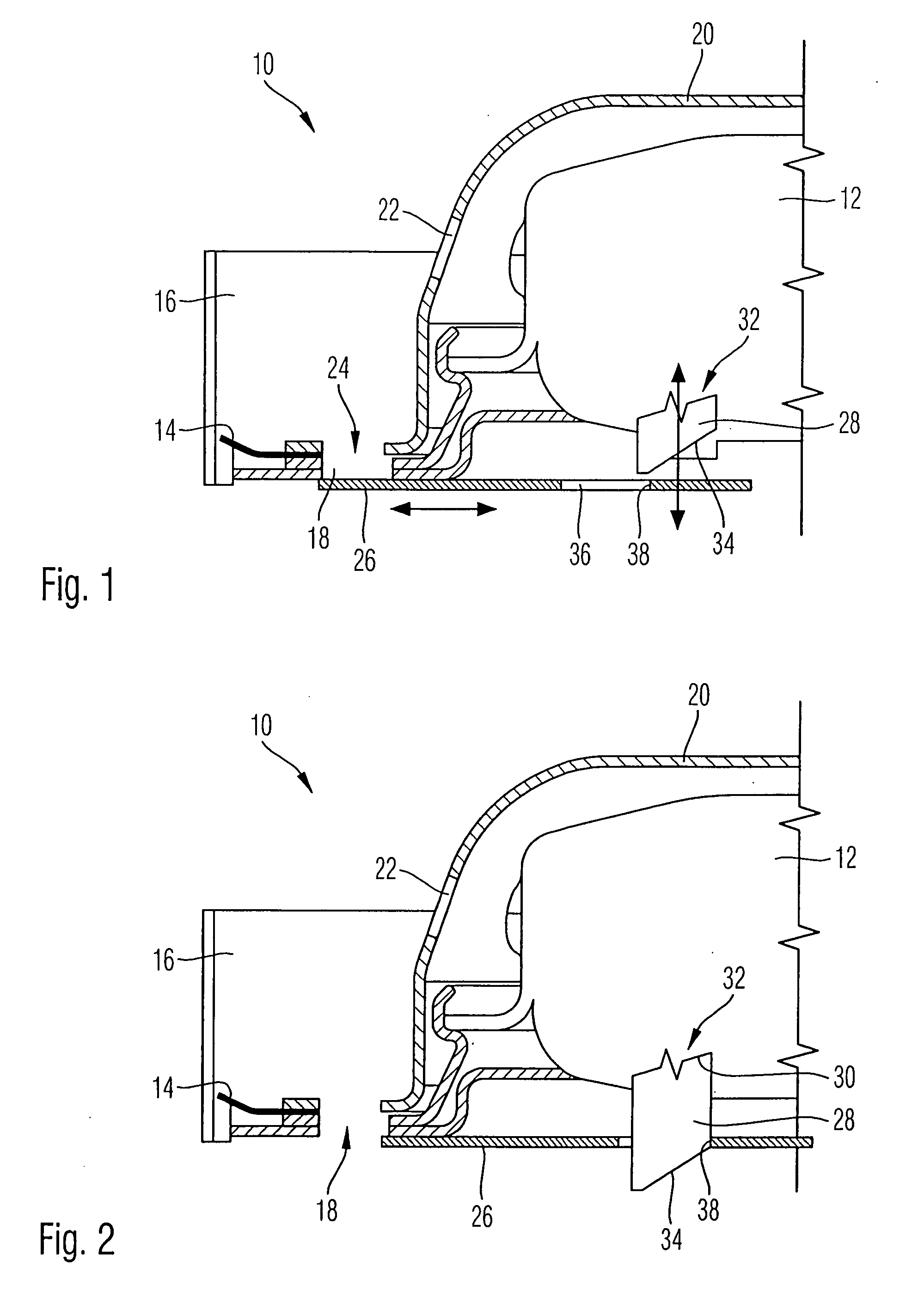
[0010] The control member advantageously has a control edge that slides along an edge of the slide element when it is subjected to compressed gas. In particular, the control edge encloses an acute angle with the direction of movement of the control member as well as with the direction of movement of the slide element. This results in a simple mechanism for moving the slide element when the control member is actuated.
[0011] According to a second embodiment of the invention, the control member can be moved between a locking position in which it affixes the slide element relative to the rigid component, and a releasing position in which the slide element can change its position. Hence, the control member is configured here as a kind of releasing mechanism that, when actuated, releases the previously affixed slide element so that it can move out of the closed position into the open position.
[0012] Advantageously, a spring element is provided that urges the slide element into the open position. In this manner, it is achieved that, after the slide element has been released by the control member, the slide element is reliably moved into the open position.
[0016] According to a preferred embodiment, the gas generator is a multi-stage gas generator. In this case, precautions can be taken to ensure that the control member is only subjected to compressed gas from the gas generator when a later stage, for instance, the second stage of the gas generator, is ignited. As a result, the gas bag initially deploys quickly while the discharge opening is closed and, when the later stage is ignited, the discharge opening is exposed in order to provide the vehicle occupant with a softer gas bag.
[0017] When the control member is subjected to compressed gas, it is preferably moved in a direction that is perpendicular to the direction of movement of the slide element. Consequently, when the control member is subjected to compressed gas, it is preferably moved downwards in the vertical direction, thus horizontally moving a slide element arranged below the gas generator on the rigid component of the gas bag module in order to expose the discharge opening formed in the rigid component. This translates into a particularly space-saving configuration.

Problems solved by technology

Such slides are moved, for example, magnetically or by means of an electric motor and are consequently very complex and relatively slow.
However, such a system with electronic sensors is relatively complex and thus expensive.
Another drawback is the fact that installation space has to be made available in the module housing for the flap and for the explosive bolt.

Method used


Image

  • Gas bag module
  • Gas bag module
  • Gas bag module

Examples


first embodiment

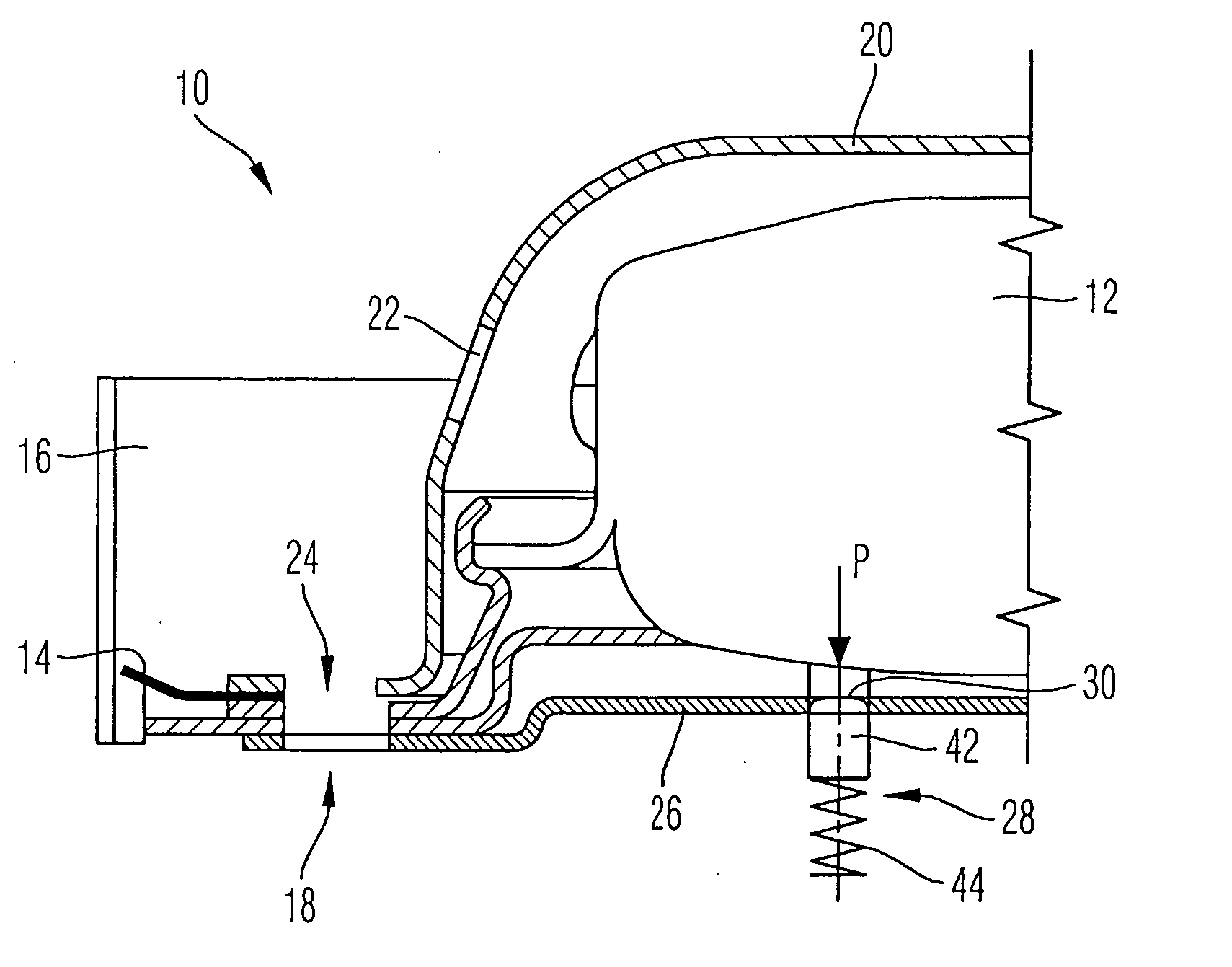
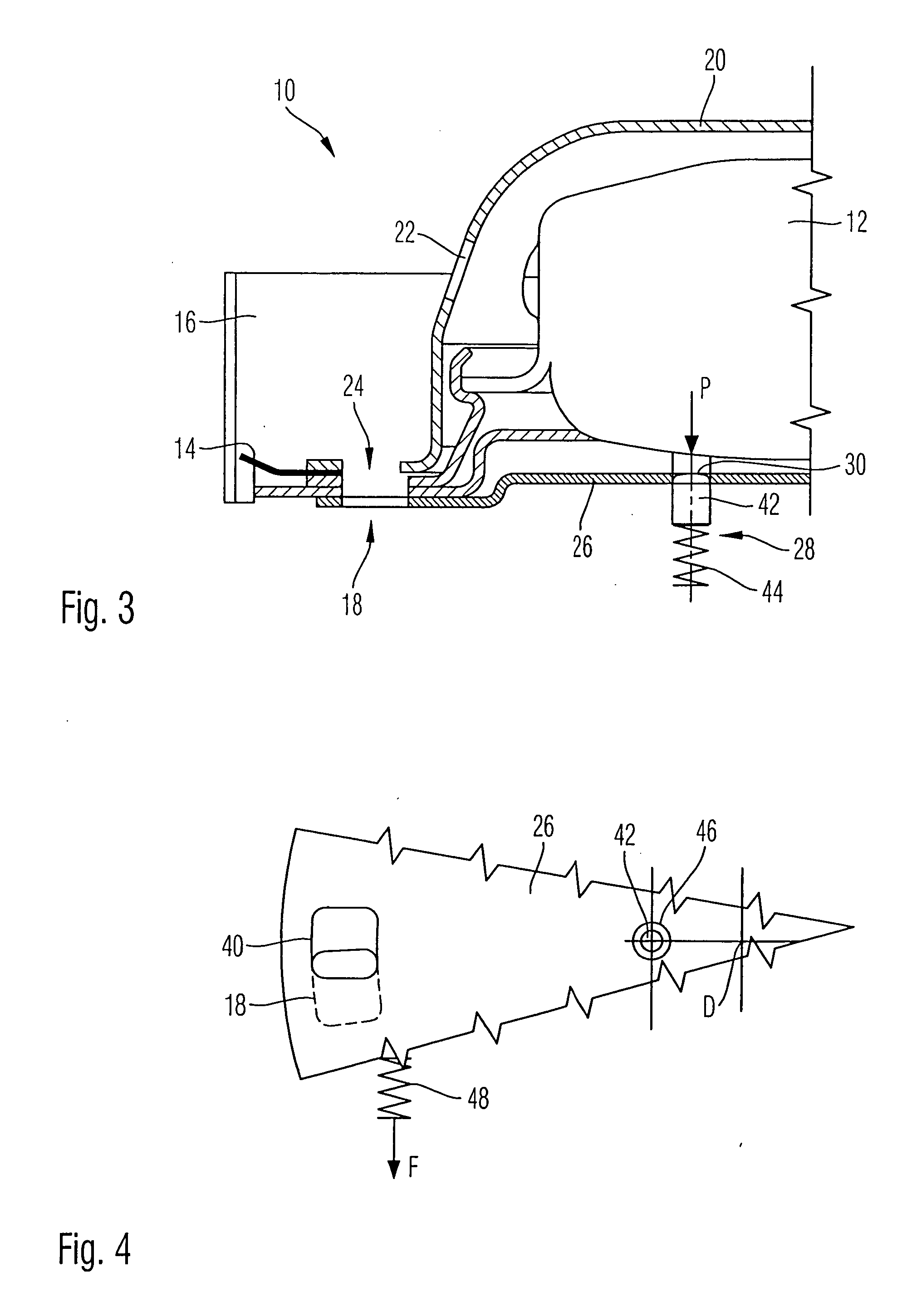
[0025]FIGS. 3 and 4 show another embodiment of the gas bag module 10 according to the invention; the same components have the same reference numerals and only the differences from the first embodiment will be discussed below.

second embodiment

[0026] The slide element 26 is configured as a rotary valve element, i.e. as a plate that is rotatably mounted in point D on the generator support 16. As an alternative, a linearly movable plate, as described with reference to FIGS. 1 and 2, can likewise be employed. The slide element 26 has an opening 40 that can be made to coincide with the discharge opening 18. The control member 28 comprises a locking pin 42 as well as a spring 44 that holds the locking pin 42 so as to engage with a recess 46 in the slide element 26 (see FIG. 3).

[0027] Another spring 48 is provided that is supported, for example, on the generator support 16 and that urges the slide element 26 into its open position. This spring 48 can be a helical spring, a coiled torsion spring or, as shown in FIG. 4, a tension spring.

[0028] In the initial situation shown in FIG. 3 immediately after the ignition of the gas generator 12, the discharge opening 18 is at first mainly closed by the slide element 26, i.e. the two o...


PUM


Abstract

A gas bag module for a vehicle occupant restraint device has a gas generator for inflating a gas bag, at least one discharge opening which is formed in a rigid component of the gas bag module and through which gas generated by the gas generator can be discharged, and a slide element that is adjustable between a closed position in which it at least largely closes the discharge opening, and an open position in which it exposes the discharge opening. A control member for the slide element is provided, the control member having a pressure surface that can be subjected to the pressure of the gas generated by the gas generator so that, when a specific pressure is present, the control member effectuates a change in the position of the slide element.

Description

TECHNICAL FIELD [0001] The present invention relates to a gas bag module for a vehicle occupant restraint device. BACKGROUND OF THE INVENTION [0002] Normally speaking, the gas bag of a gas bag module should be inflated as quickly as possible with gas generated by a gas generator. In certain cases, however, it is desirable not to inflate the gas bag with the entire volume of gas available but rather, to put it in more general terms, to discharge gas, which is why the gas bag module is provided with discharge openings that are exposed so that the pressure in the gas bag can be limited. [0003] The literature describes numerous solution possibilities that have the aim of regulating the internal pressure and thus the restraining effect of the gas bag as a function of the load in case of an accident. Thus, for example, gas bag modules are known in which a discharge opening in a housing of the module is covered in the closed state by a slide or the like that can be moved in order to expose...

Claims


Application Information

Patent Timeline
Patent Type & Authority Applications(United States)
IPC IPC(8): B60R21/26B60R21/276B60R21/20B60R21/217
CPCB60R21/217B60R2021/2765B60R21/276
Inventor STAUDT, HOLGERDERRICK, JOHN-OLIVER
Owner TRW AUTOMOTIVE SAFETY SYST
Learn More