
Communication control device and method

a communication control device and communication control technology, applied in the field of communication devices and communication systems, can solve the problems of inconvenient method selection, inconvenient use of address designation, and many home electrical devices without text entry input interfaces, so as to avoid inconsistencies in the determinations made by both parties

Inactive Publication Date: 2007-01-04
PANASONIC CORP
View PDF10 Cites 5 Cited by
  • Summary
  • Abstract
  • Description
  • Claims
  • Application Information

AI Technical Summary

Benefits of technology

[0015] For example, user A of an IP telephone unit a1 (corresponding to a communication control device) may wish to transmit a still image to user B who is talking on an IP telephone unit b1 (first communication function). In such an example, the IP telephone unit a1 will obtain the communication address of a communication device b2 belonging to user B which can receive a still image, e.g., the facsimile number of a facsimile device, from the IP telephone unit b1. The IP telephone unit a1 will transmit the obtained facsimile number to a facsimile device (corresponding to a communication device a2) connected by LAN (corresponding to a second communication function). When the facsimile device (communication device a2) receives the facsimile number, it will call the number (third communication function). In other words, the IP telephone unit a1 having the communication control device will obtain the communication address necessary for the third communication function during a conversation, and notify the communication device a2 with the second communication function. In this way, users can use a plurality of communication devices simultaneously in order to perform various types of communication in a flexible manner.
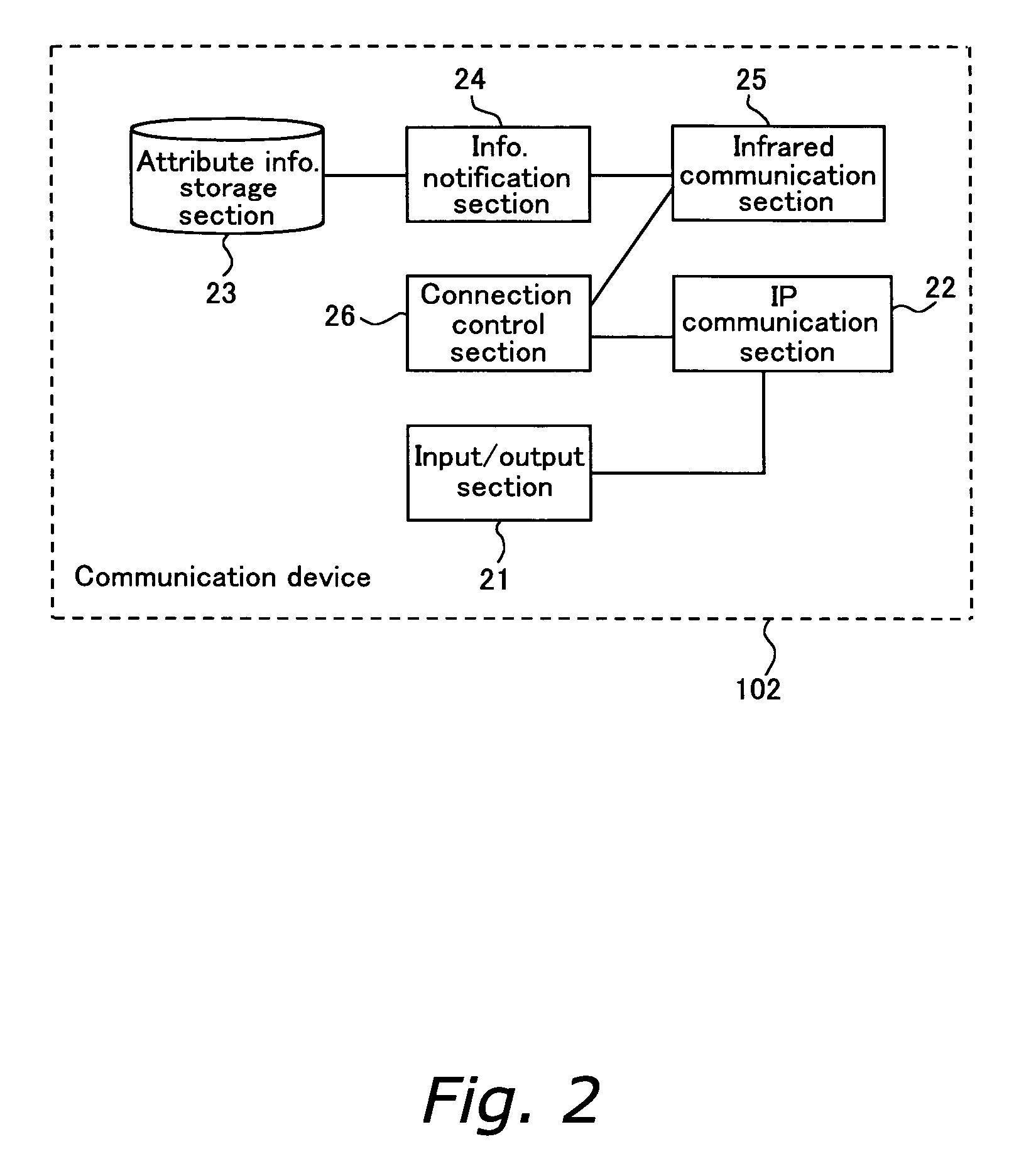
[0017] The second communication function may be, for example, infrared communication, Bluetooth (registered trademark), wireless / wired LAN, USB and the like. This function allows the attribute information of the communication device to be retrieved from the communication device itself and stored in the first attribute information storage unit. Of course, the user can set the attribute information.
[0019] Since candidates for the plurality of communication devices are transmitted to the other party, the other party is able to select the communication device which fulfills the requirements. Thus, the variations in the combination of communication devices used by two parties will increase, and users can enjoy more convenience.
[0021] Further, in accordance with the evaluation rules to be applied, it is preferable to operate a scheduler, or a user state control device for managing a schedule of the user with the communication control device. This allows precisely selecting candidates for the communication devices which are appropriate for the user based on various information.
[0027] Since both parties exchange the evaluation results, and the optimal combination is determined based on the sum of the evaluation results of both parties, inconsistencies in the determinations made can be avoided.
[0042] Since both parties exchange the evaluation results and the optimal combination is determined based on the sum of the evaluation results of both, a combination of communication devices that is biased toward one party can be prevented. Further, inconsistencies in the determinations made by both parties can be avoided.

Problems solved by technology

However, in general, many home electrical devices do not include an input interface suitable for text entry, e.g., a personal computer keyboard.
Thus, the task of designating an address is often very cumbersome for users.
However, this method is very cumbersome, and errors in the address often occur.
Furthermore, when there are a number of devices around the user or the other party, it is difficult to know the capabilities of all those devices and then find the appropriate device.

Method used


Image

  • Communication control device and method
  • Communication control device and method
  • Communication control device and method

Examples


embodiment 1

[Structure]

(1) Overall Structure

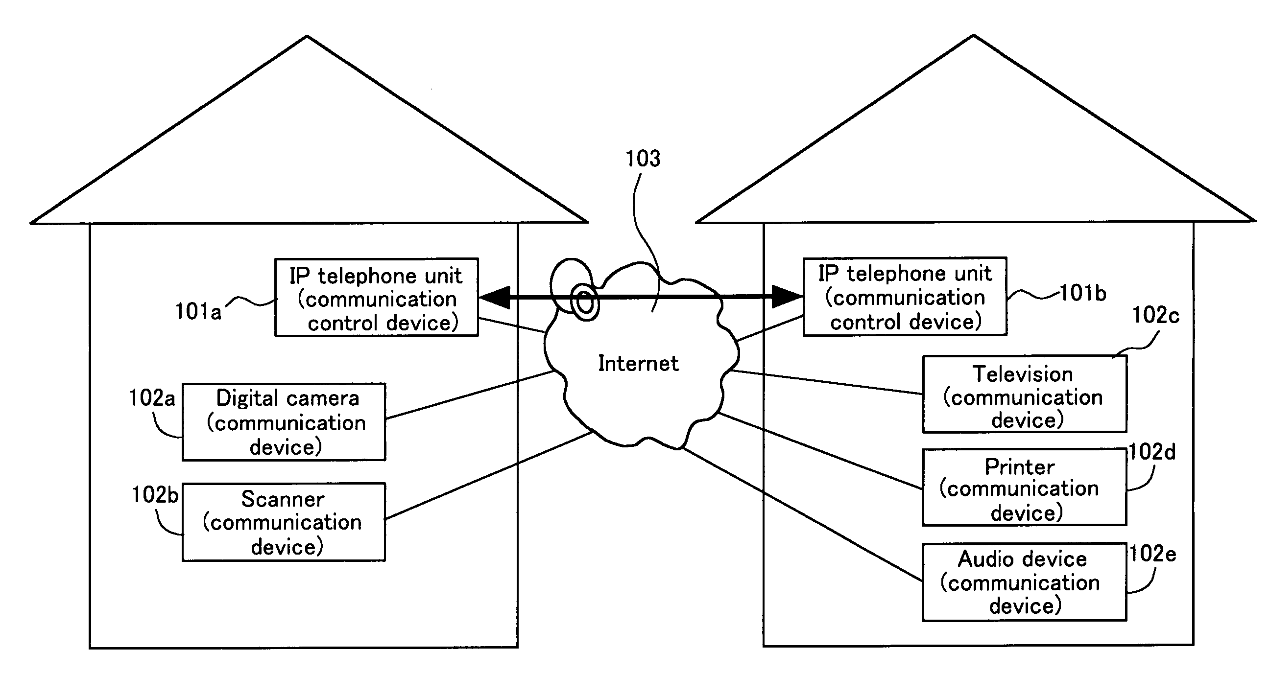
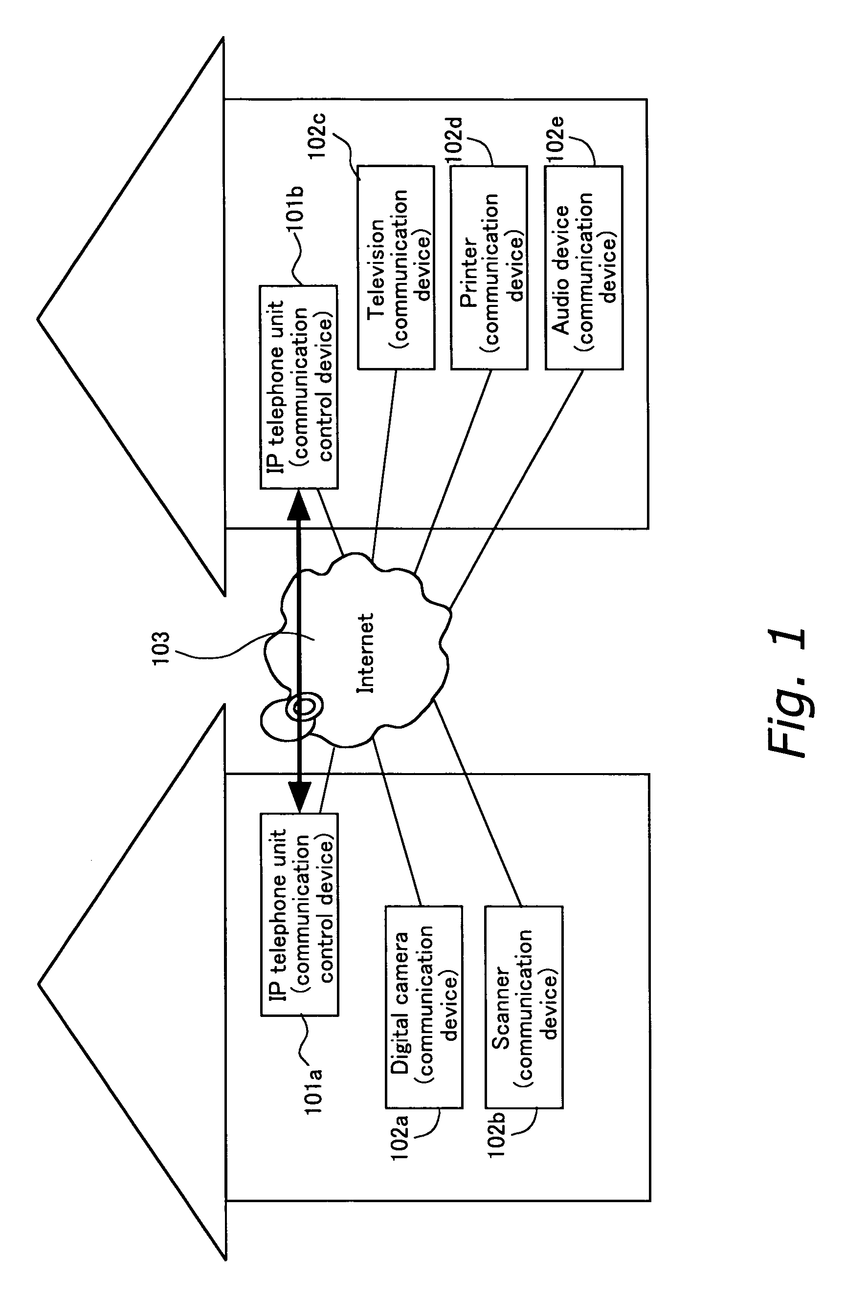
[0072]FIG. 1 is a diagram showing an example of communication control devices and communication devices connected to each other according to the present invention. IP telephone units 101a and 101b are communication control devices according to the present embodiment. User A uses the IP telephone unit 101a, and user B uses the IP telephone unit 101b. They are respectively connected to the Internet. The IP telephone units 101a and 101b communicate by means of an IP telephone function.

[0073] In the present embodiment, IP telephone units are used as communication control devices 101. However, terminals having an e-mail function and / or instant messaging function may also be used as communication control devices. Alternatively, terminals having a general analog telephone function, ISDN, or cell phone function can be used as communication control devices. In other words, any type of device can be used as a communication control device as long as both use...


PUM


Abstract

People communicating with each other in remote places can easily connect their communication devices. For example, a user A of an IP telephone unit a1 may have a desire to transmit a still image to a user B talking on an IP telephone unit b1. In such a case, from the IP telephone unit b1, the IP telephone unit a1 obtains the facsimile number of a communication device belonging to user B which can receive still images, for example, a facsimile. The IP telephone unit a1 can transmit the obtained facsimile number to the facsimile device a2 connected by LAN. The facsimile device a2 which has received the number calls the received facsimile number. In other words, the IP telephone unit a1 which includes the communication control device obtains the communication address required for a third communication during a call, and notifies the communication device a2 of the address with the second communication function.

Description

TECHNICAL FIELD [0001] The present invention relates to a communication device and a communication system that employs a network such as the Internet in order to provide a remote communication function to a user. BACKGROUND ART [0002] Recently, more and more home electrical appliances used in everyday life, such as televisions, digital cameras, car navigation system, and the like, have a communication function utilizing the Internet or the like. It is thought that in the future, many home electrical devices used in everyday life will have a communication function utilizing the Internet or the like, and thus will allow one device to exchange various data such as images, audio, text, and the like with other designated devices. For example, it will be possible to transmit an image taken with one's digital camera to another designated device such as cell phone, car navigation system, or the like, via the Internet or the like to be displayed thereon, or transmit that image to a designate...

Claims


Application Information

Patent Timeline
Patent Type & Authority Applications(United States)
IPC IPC(8): G06F15/16H04L12/66H04L29/06H04M7/00
CPCH04L12/66H04L29/06027H04L65/1083H04M7/0027H04M7/0024H04L65/1094H04L65/1101
Inventor HIRAI, JUNICHISUGIYAMA, KEIJITAKEMURA, MASASHI
Owner PANASONIC CORP
Learn More