Receiver, transmitter and variable bandwidth transmission method

a transmission method and transmitter technology, applied in the field of receivers, transmitters and variable bandwidth transmission methods, can solve the problems of limited transmission bandwidths used in communication, limited frequency spectrum resources, and limited transmission bandwidths in time domains, so as to simplify the interface and avoid unwanted transition responses

Inactive Publication Date: 2007-01-04
NOKIA SOLUTIONS & NETWORKS OY
View PDF1 Cites 8 Cited by
  • Summary
  • Abstract
  • Description
  • Claims
  • Application Information

AI Technical Summary

Benefits of technology

[0014] The invention provides several advantages. The proposed structure will simplify the interface between radio frequency parts and base band parts (RF-BB) since the transmitter or receiver filter impulse responses do not have to change within real time operation. Thus, unwanted transition responses can be avoided. The transmission bandwidth can be determined in the base band processing after the reception of a frame or a time slot. The proposed structure enables blind transmission bandwidth detection in receiver base band processing. When the transmission bandwidth is detected, the sub-band signals can be combined.

Problems solved by technology

In telecommunication systems, the frequency spectrum is a limited resource.
Therefore, transmission bandwidths used in communication are usually limited.
Transmissions are also limited in the time domain.
However, because of the well-known Nyquist Criterion, square pulse shapes cannot be transmitted over a band-limited channel, because square pulse shapes occupy an infinite bandwidth and inter-symbol interference will happen.
This leads to a need to have variable bandwidth filters in transmitters and receivers.
From the implementation point of view, the variable bandwidth transmission is a problem in transmitter and especially in receiver filters.
Changing the filter impulse response by changing the filter in real time receiver filter operation is difficult and could result undesired transition responses causing undesirable interference to adjacent channels or to adjacent timeslots.
The receiver may have also another problem if the transmission bandwidth is not known beforehand.

Method used


Image

  • Receiver, transmitter and variable bandwidth transmission method
  • Receiver, transmitter and variable bandwidth transmission method
  • Receiver, transmitter and variable bandwidth transmission method

Examples


Embodiment Construction

[0028] The present invention is applicable to various telecommunication systems. Typical examples of a system to which the invention can be applied are evolutions of the third generation cellular telecommunication systems, UMTS (Universal Mobile Telecommunications System). However, the invention is not limited to UMTS or any other cellular telecommunications system, as one skilled in the art is aware.

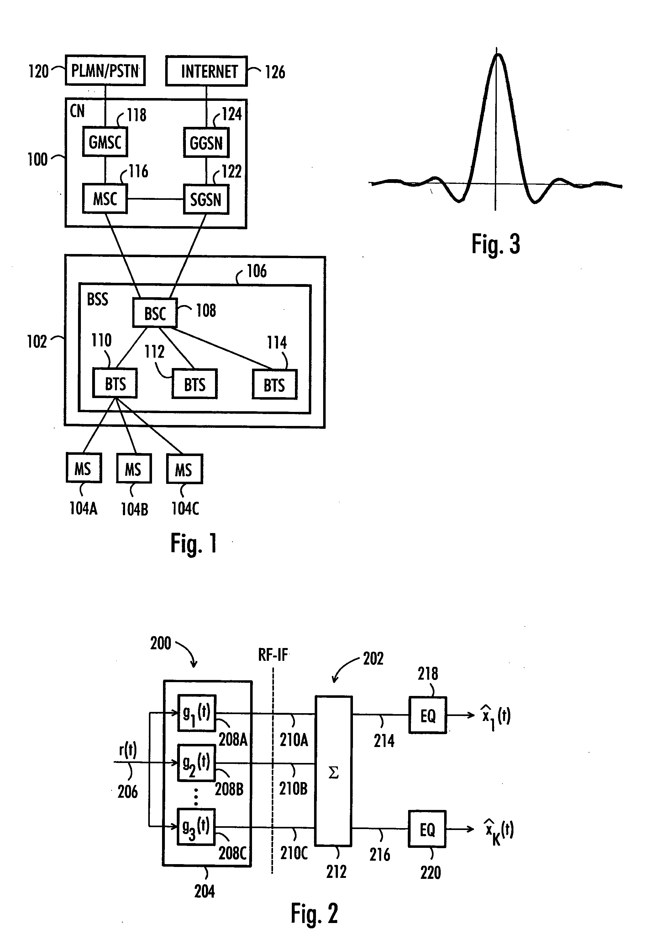
[0029] With reference to FIG. 1, examine an example of a data transmission system to which embodiments of the invention can be applied. FIG. 1 is a simplified block diagram describing the most important cellular telecommunication system parts at network element level. The structure and operation of the network elements are not described in detail, since they are commonly known.

[0030] The cellular telecommunication system may be divided into a core network (CN) 100, a radio access network (RAN) 102 and mobile stations (MS) 104A, 104B, 104C.

[0031] The RAN 102 includes a base station sy...


PUM


Abstract

Solutions for receiving and transmitting variable transmission bandwidth signal are provided. A receiver comprises square-root raised cosine filter bank, each filter of the filter bank configured to filter a subband, and an adder configured to add up the output signals of one or more filters of the filter bank to obtain a sum signal, the sum of the subbands of the one or more filters being equal to the transmission bandwidth of the received signal. A transmitter comprises a transmission filter, the roll-off factor of the transmission filter being selected on the basis of the bandwidth of the signal to be transmitted.

Description

FIELD [0001] The invention relates to transmission methods in telecommunication systems. In particular, the invention relates to systems where transmission bandwidth varies between users or where users employ variable bandwidth transmission. BACKGROUND [0002] In telecommunication systems, the frequency spectrum is a limited resource. Therefore, transmission bandwidths used in communication are usually limited. This applies both analog and digital communication systems. Transmissions are also limited in the time domain. [0003] Especially in digital communication systems, transmitted signals comprise time slots or frames, in which the signals are transmitted as pulses in finite lengths. However, because of the well-known Nyquist Criterion, square pulse shapes cannot be transmitted over a band-limited channel, because square pulse shapes occupy an infinite bandwidth and inter-symbol interference will happen. Therefore, signals are filtered prior to the transmission to shape the spectru...

Claims


Application Information

Patent Timeline
Patent Type & Authority Applications(United States)
IPC IPC(8): G10L19/02H04BH04B1/16
CPCG10L25/18H04B1/16
Inventor VAISANEN, PETRIPIIRAINEN, OLLIVAINIKKA, MARKKU
Owner NOKIA SOLUTIONS & NETWORKS OY
Why Eureka
Try Eureka