Display device and driving method of display device
a display device and driving method technology, applied in static indicating devices, instruments, electroluminescent light sources, etc., can solve the problems of difficult to realize high definition and multiple gray scales, area gray scale methods, etc., to improve display quality, reduce pseudo contours, and improve duty ratio
- Summary
- Abstract
- Description
- Claims
- Application Information
AI Technical Summary
Benefits of technology
Problems solved by technology
Method used
Image
Examples
embodiment mode 1
(Embodiment Mode 1)
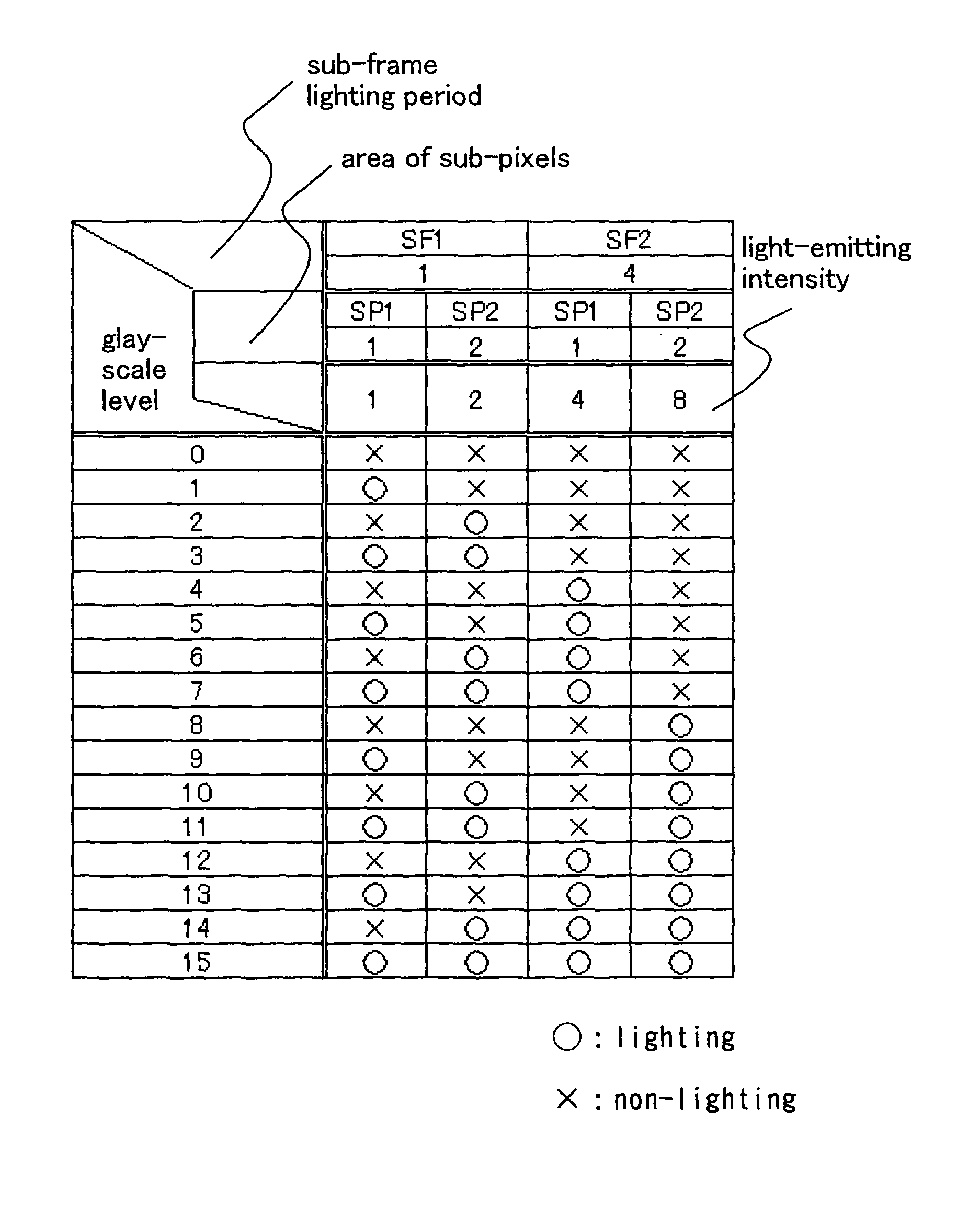
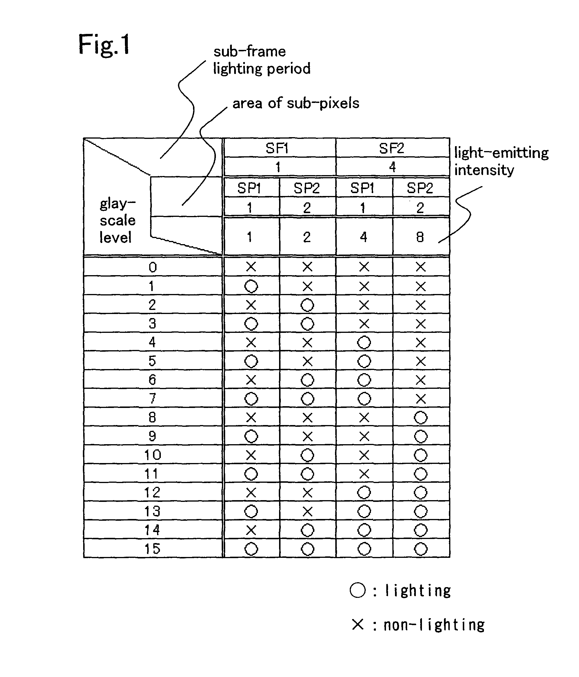
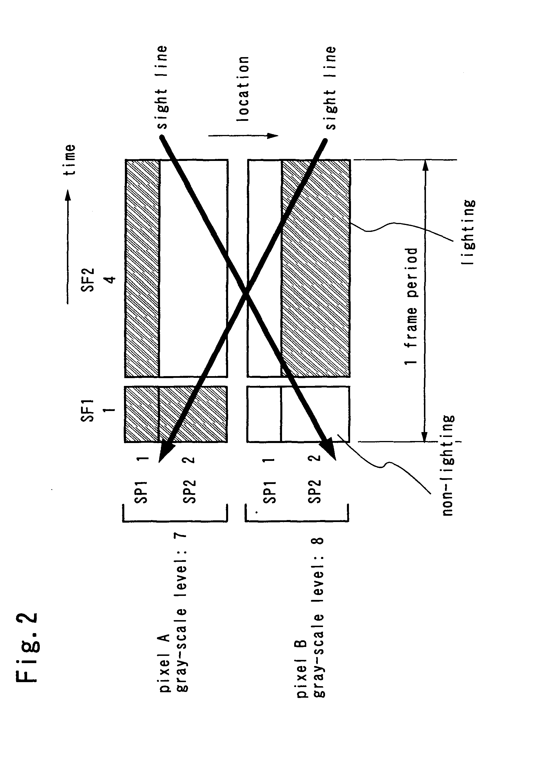
[0110] This embodiment mode will explain an example of applying a driving method of the present invention to a case of 4-bit display (16 gray scales) and a case of 6-bit display (64 gray scales).
[0111] The driving method of this embodiment mode is combined with an area gray scale method by which gray scale display is performed by dividing one pixel into a plurality of sub-pixels and controlling the number or area of lighting sub-pixels and a time gray scale method by which gray scale display is performed by dividing one frame into a plurality of sub-frames, each of which is weighted with respect to the nimber of light emissions and a light-emitting period, and then the total weight is differentiated for each gray scale. In other words, one pixel is divided into m (m is an integer number of m≧2) of sub-pixels to have an area ratio of the m sub-pixels 20:21:22: . . . :2m−3:2m−2:2m−1. In addition, one frame is divided into n (n is an integer number of n≧2) of sub-fr...
embodiment mode 2
(Embodiment Mode 2)
[0175] This embodiment mode will describe an example of a timing chart. This embodiment mode will be explained by giving, as an example, a case (FIG. 7) where one pixel is divided into two sub-pixels (SP1 and SP2) so that an area ratio of each sub-pixel becomes 1:2 and one frame is divided into three sub-frames (SF1, SF2, and SF3) so that a ratio of a lighting period in each sub-frame becomes 1:4:16.
[0176] Here, the sub-pixels respectively have the following area: SP1=1 and SP2=2, and the sub-frames respectively have the following lighting periods: SF1=1, SF2=4, and SF3=16.
[0177] First, FIG. 24 shows a timing chart in the case where a period where a signal is written to a pixel and a lighting period where are separated.
[0178] Note that a timing chart is a diagram showing light emission of a pixel in one frame, and a horizontal indicates a time whereas a vertical direction indicates a row where pixels are arranged.
[0179] First, signals for one screen are inputt...
embodiment mode 3
(Embodiment Mode 3)
[0249] This embodiment mode will describe a layout of a pixel in a display device according to the present invention. As an example, FIG. 35 shows a layout diagram of the circuit diagram shown in FIG. 25. Note that the circuit diagram and the layout diagram are not limited to FIG. 25 and FIG. 35.
[0250] First and second select transistors 3511 and 3521, first and second driving transistors 3513 and 3523, first and second holding capacitors 3512 and 3522, electrodes 3514 and 3524 of first and second light-emitting elements, a signal line 3515, a power supply line 3516, and first and second scanning lines 3517 and 3527 are arranged in FIG. 35. As for a sub-pixel 1 (SP1), a source electrode and a drain electrode of the first select transistor 3511 are each connected to the signal line 3515 and a gate electrode of the first driving transistor 3513. A gate electrode of the first select transistor 3511 is connected to the first scanning line 3517. A source electrode and...
PUM
 Abstract
Description
Claims
Application Information
 - R&D
- Intellectual Property
- Life Sciences
- Materials
- Tech Scout
- Unparalleled Data Quality
- Higher Quality Content
- 60% Fewer Hallucinations
Browse by: Latest US Patents, China's latest patents, Technical Efficacy Thesaurus, Application Domain, Technology Topic, Popular Technical Reports.
© 2025 PatSnap. All rights reserved.Legal|Privacy policy|Modern Slavery Act Transparency Statement|Sitemap|About US| Contact US: help@patsnap.com


