
Ion-removing apparatus

Inactive Publication Date: 2007-01-04
TOYOTA BOSHOKU KK +1
View PDF2 Cites 10 Cited by
  • Summary
  • Abstract
  • Description
  • Claims
  • Application Information

AI Technical Summary

Benefits of technology

[0008] It is accordingly an object of the present invention to provide techniques for efficiently removing plural kinds of ions contained in a fluid and for enabling ion exchange resins to be used for their usable life periods, thereby improving the economical aspect.
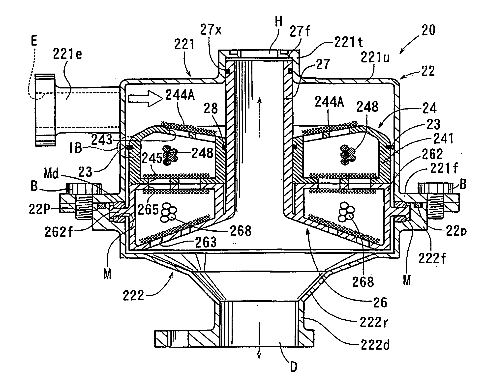
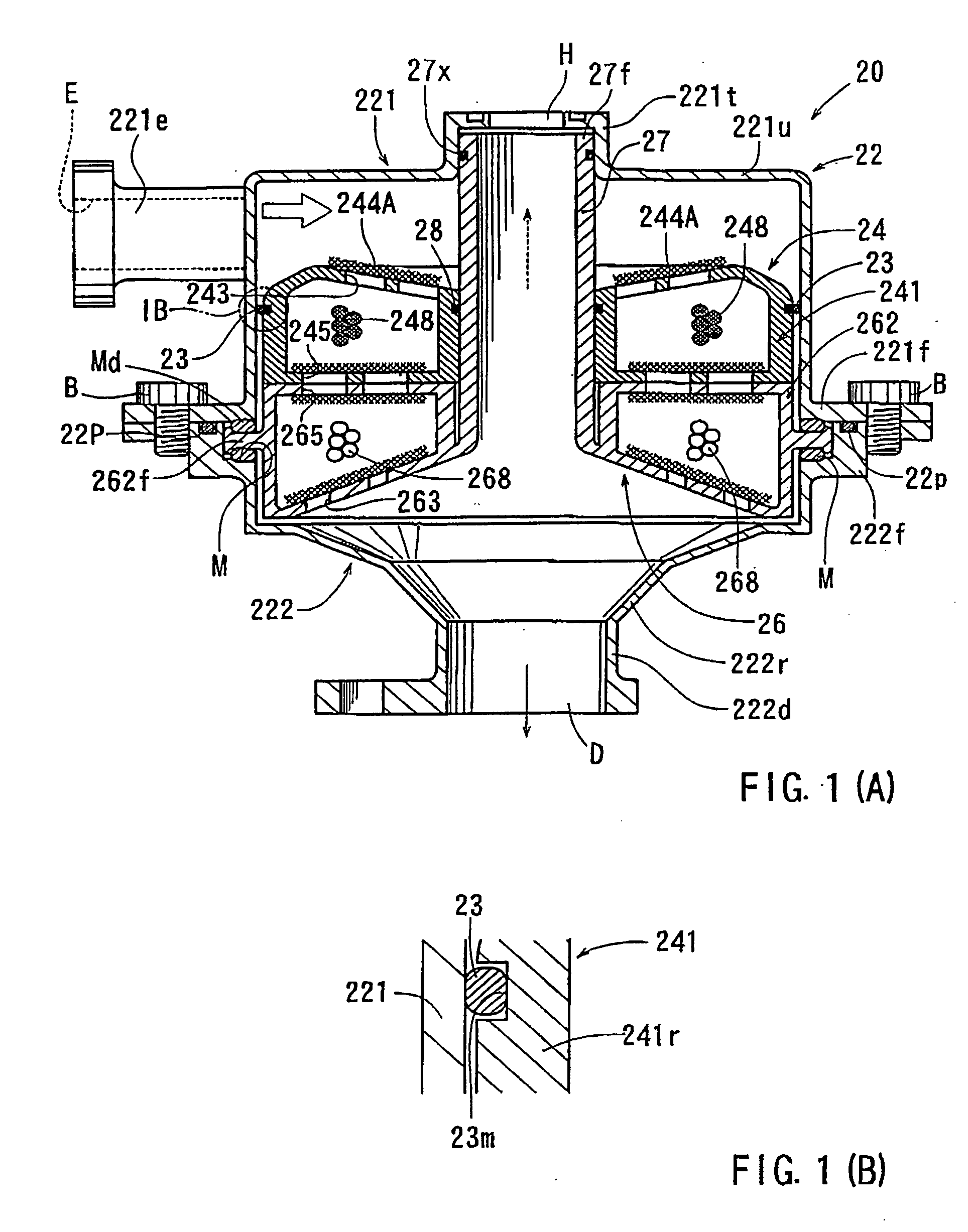
[0010] With this arrangement, the first ion may be removed as the fluid flows through the first ion-removing unit. Then, the second ion may be removed as the fluid further flows through the second ion-removing unit. After leaving the second ion-removing unit, the liquid contained in the fluid is discharged via the liquid discharge port and the gas contained in the fluid is discharged via the gas discharge port. In this way, the fluid flows through the first and second ion-removing units that are arranged in series with each other. Therefore, the first and second ions can be effectively removed.
[0011] In addition, the first ion-removing unit has become to be no longer usable, while the second ion-removing unit is still usable, it is possible to replace only the first ion-removing unit. Therefore, both the first and second ion-removing units can be used until the ends of their usable lives, so that the economical aspect can be improved.
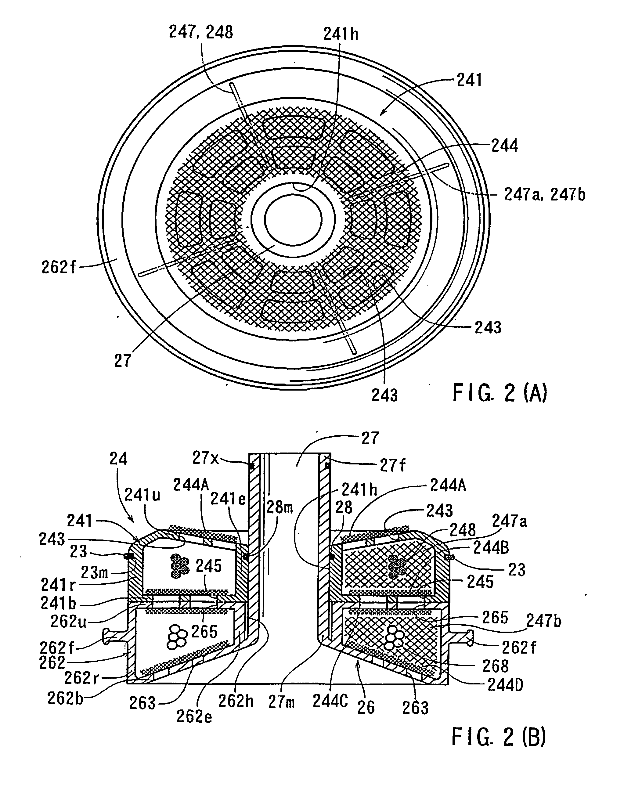
[0014] Because the inlet openings and outlet openings of the container are covered by the net sheets, the ion exchange resin granules can be reliably held within the container. In addition, the sizes of the inlet openings and the outlet openings can be freely determined independently of the size of the ion exchange resin granules. Further, because the net sheets may prevent any foreign particles from entering the container, the ion exchange resin granules may be protected from any interaction by the foreign particles. In addition, free spaces between the ion exchange granules can be ensured to prevent potential clogging by the foreign particles.
[0016] This arrangement facilitates the assembling and disassembling operations of the first and second ion-removing units. Therefore, each of the first and second ion-removing units can easily be replaced.
[0017] Preferably, each of the first and second containers defines a inner space that is segmented in the circumferential direction by a plurality of net sheets. Therefore, the movement of the exchange resin granules in the circumferential direction within the container may be limited by the net sheets. As a result, it is possible to prevent potential accumulation of the ion exchange resin granules to anywhere along the circumferential direction of the container.

Problems solved by technology

In addition, the first ion-removing unit has become to be no longer usable, while the second ion-removing unit is still usable, it is possible to replace only the first ion-removing unit.

Method used


Image

  • Ion-removing apparatus
  • Ion-removing apparatus
  • Ion-removing apparatus

Examples


Embodiment Construction

[0024] Each of the additional features and teachings disclosed above and below may be utilized separately or in conjunction with other features and teachings to provide improved ion-removing apparatus. Representative examples of the present invention, which examples utilize many of these additional features and teachings both separately and in conjunction with one another, will now be described in detail with reference to the attached drawings. This detailed description is merely intended to teach a person of skill in the art further details for practicing preferred aspects of the present teachings and is not intended to limit the scope of the invention. Only the claims define the scope of the claimed invention. Therefore, combinations of features and steps disclosed in the following detailed description may not be necessary to practice the invention in the broadest sense, and are instead taught merely to particularly describe representative examples of the invention. Moreover, vari...


PUM

PropertyMeasurementUnit
Sizeaaaaaaaaaa
Gravityaaaaaaaaaa

Abstract

An ion-removing apparatus includes a housing, a first ion-removing unit and a second ion-removing unit. The housing includes an inlet port, a liquid discharge port and a gas discharge port. The first ion-removing unit is disposed within the housing, so that the fluid that has entered the housing via the inlet port flows through the first ion-removing unit. The first ion-removing unit serves to remove a first ion, such anions, contained in the fluid. The second ion-removing unit is disposed within the housing, so that the fluid that has flown though the first ion-removing unit flows through the first ion-removing unit. The second ion-removing unit serves to remove a second ion, such as cations contained in the fluid. The liquid contained in the fluid that has flown through the second ion-removing unit is discharged from the liquid discharge port. The gas contained in the fluid that has flown through the second ion-removing unit is discharged from the gas discharge port.

Description

[0001] This application claims priority to Japanese patent application serial number 2005-176289, the contents of which are incorporated herein by reference. BACKGROUND OF THE INVENTION [0002] 1. Field of the Invention [0003] The present invention relates to ion-removing apparatus for removing ions contained in a fluid. [0004] 2. Description of the Related Art [0005] Various types of ion-removing apparatus are known. For example, Japanese Laid-Open Patent Publication No. 2002-313404 teaches an ion-removing apparatus 50 shown in FIG. 4. The ion-removing apparatus 50 is designed for removing ions contained in a fluid that is discharged from a fuel cell 51. The ion-removing apparatus 50 includes a container 52 and an ion exchange resin 54. The container 52 stores water. The ion exchange resin 54 is disposed within the container 52 and is immersed into the water. The fluid that has been discharged from the fuel cell 51 may flow through the water within the container 52, so that the liqu...

Claims


Application Information

Patent Timeline
IPC IPC(8): C02F1/461
CPCC02F1/42C02F2001/422C02F2001/425Y02E60/50H01M8/04097H01M8/04164C02F2201/002
Inventor ARAI, YASUNARIMORITA, AKISHINAKAGAKI, NOBUHIKOSEKINE, HIROYUKI
Owner TOYOTA BOSHOKU KK
Learn More