
Fiber optic cable having strength component

a fiber optic cable and component technology, applied in the field of fiber optic cables, can solve the problems of difficult access to optical fibers, difficult manufacture of cables, and high production costs of cables, so as to avoid stress-induced optical attenuation, prevent breakage, and improve optical performance

Inactive Publication Date: 2006-12-28
CORNING CABLE SYST LLC
View PDF9 Cites 142 Cited by
  • Summary
  • Abstract
  • Description
  • Claims
  • Application Information

AI Technical Summary

Benefits of technology

This patent describes a special type of fiber optic cable that has extra reinforcement to make it stronger and more durable. This added layer helps keep the cables from getting bent too much, which could cause damage or reduce their ability to transmit light signals. It also makes sure that if there are any breaks in the cable, they don't happen because of pressure caused by bending. Overall, this design ensures better quality and reliability when working with fiber optic cables.

Problems solved by technology

The technical problem addressed in this patent text is the need for a simpler and more cost-effective fiber optic cable design that includes few components but still maintains its preferred bend without experiencing unwanted pressure or rotation when handled and deployed. Additionally, it seeks to improve access to the optical transmission components within the cable while keeping its size compact enough to meet various installation needs.

Method used


Image

  • Fiber optic cable having strength component
  • Fiber optic cable having strength component
  • Fiber optic cable having strength component

Examples


Embodiment Construction

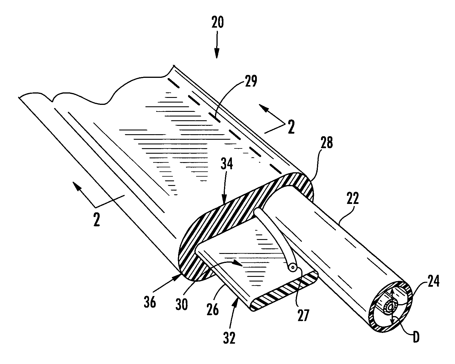
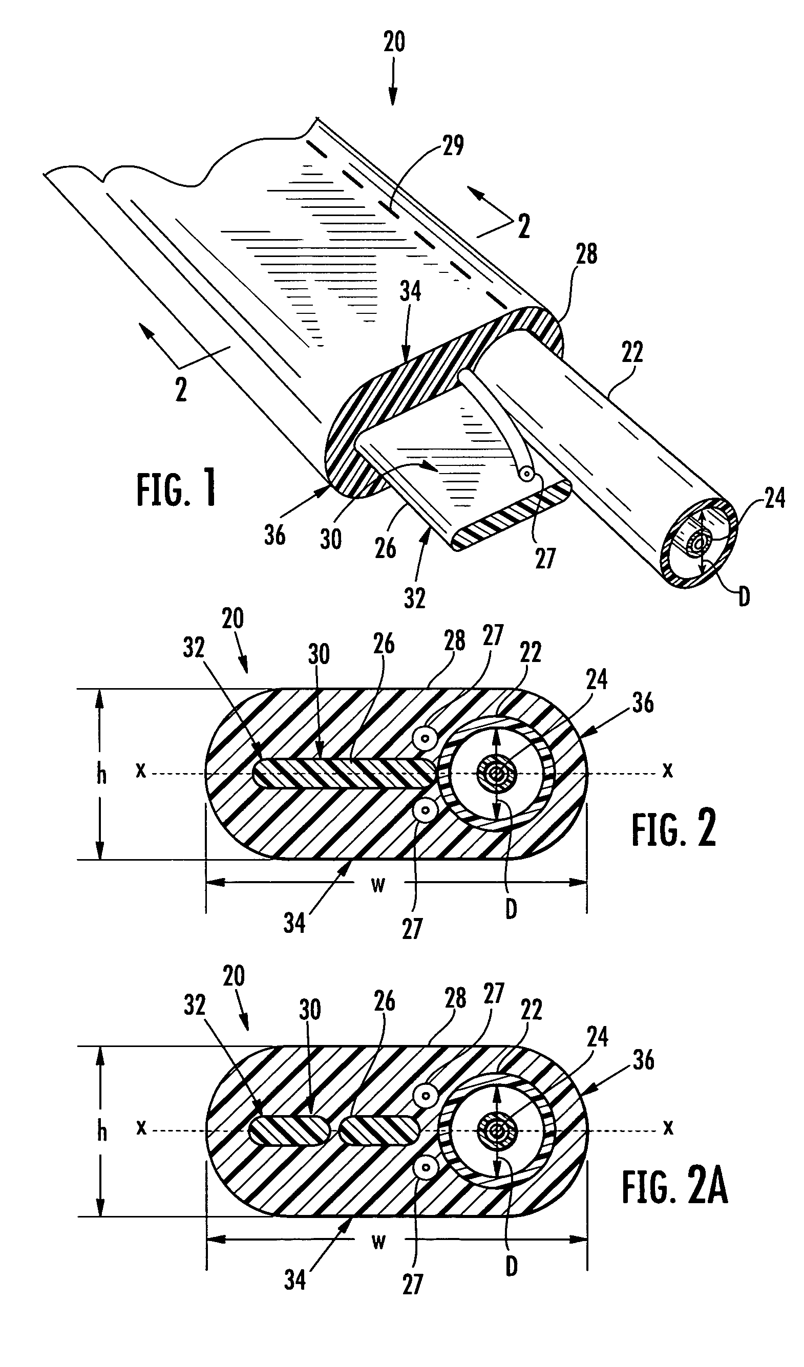
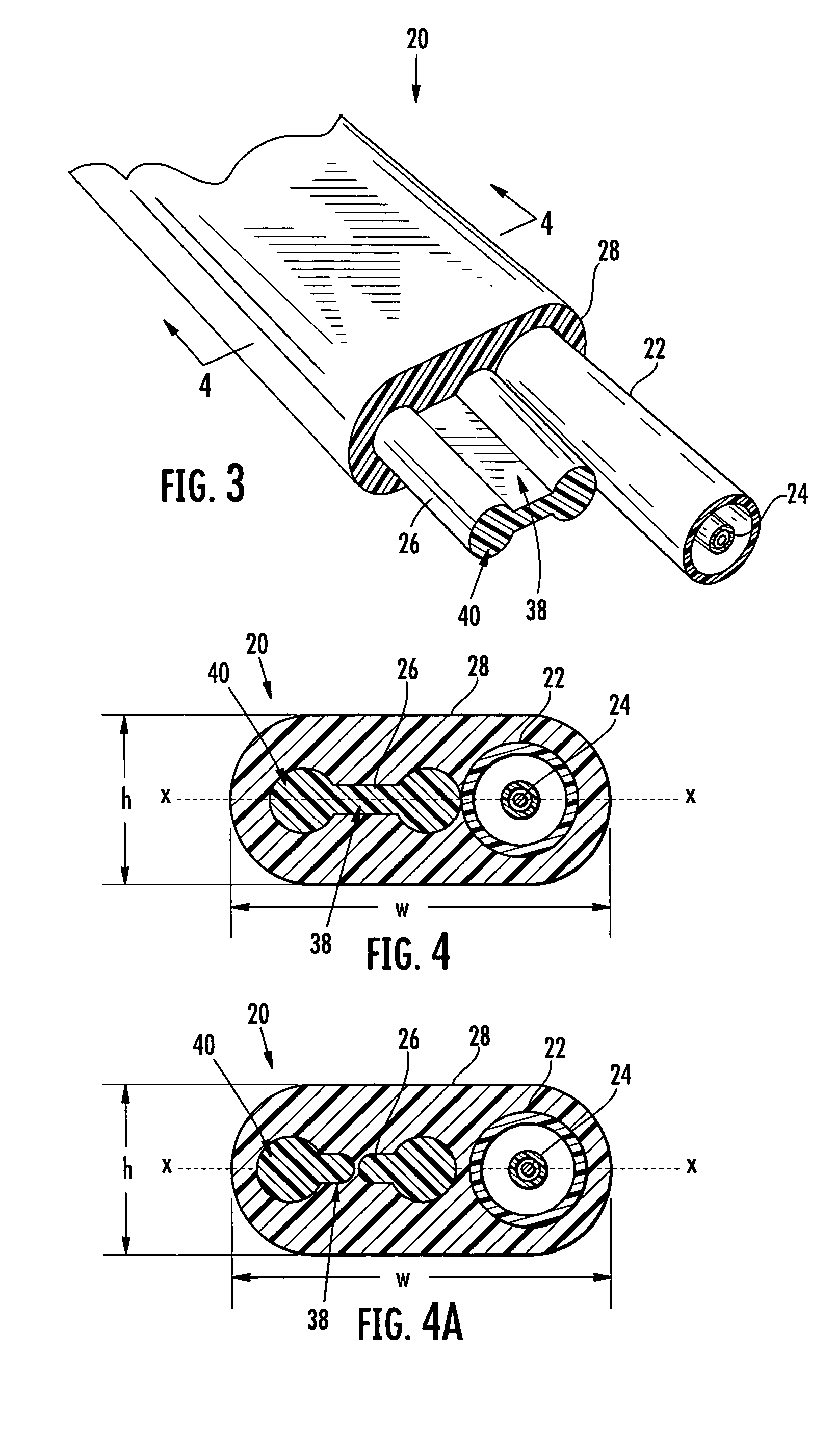
[0018] Reference will now be made in detail to the present preferred embodiments of the invention, and examples of which are illustrated in the accompanying drawings. Whenever possible, the same reference numerals will be used throughout the drawings to refer to the same or like parts. A fiber optic cable including at least one optical transmission component and a preferential bend strength component having at least one predetermined shape is shown in FIGS. 1-6 and is designated generally throughout by reference number 20. In all embodiments shown, the fiber optic cable 20 is flexible, easy to route and has a preferential bend characteristic. Preferably, the fiber optic cable is an outside plant drop cable designed for aerial self-support, overlash, placement within a conduit or direct-buried applications.

[0019] Referring specifically to FIGS. 1 and 2, an exemplary embodiment of a fiber optic cable including a preferential bend strength component having a predetermined shape is sho...


PUM


Abstract

A fiber optic cable including at least one optical transmission component, a strength component axially aligned with the fiber optic cable and having a predetermined elongate shape and a cable sheath surrounding the at least one optical transmission component and the strength component and having a predetermined geometric configuration. A strength component positioned generally adjacent the at least one optical transmission component such that the strength component and the at least one optical transmission component are positioned along a common axis in order to provide the fiber optic cable with a preferential bend. A strength component having a predetermined elongate shape to protect against crush, impact and rotational forces applied to the cable.

Description


Claims


Application Information

Patent Timeline
Owner CORNING CABLE SYST LLC
Learn More