
Orthopedic polycentric hinge

a hinge and polycentric technology, applied in the field of orthopaedic articulating braces, can solve the problems of inability to achieve the intended purpose of hinges, inability to secure hinges, and the knee intended to be protected could suffer further trauma, so as to prevent pin disassembly

Inactive Publication Date: 2006-12-21
LINEBERGER BRADLEY
View PDF21 Cites 16 Cited by
  • Summary
  • Abstract
  • Description
  • Claims
  • Application Information

AI Technical Summary

Benefits of technology

[0010] The primary object of the present invention is to provide an improved and essentially fail proof cover for the limit pins for preventing disassociation of the pins from their respective apertures.
[0011] A further object of the invention is to provide improved means for retaining the pins in association with the hinge.
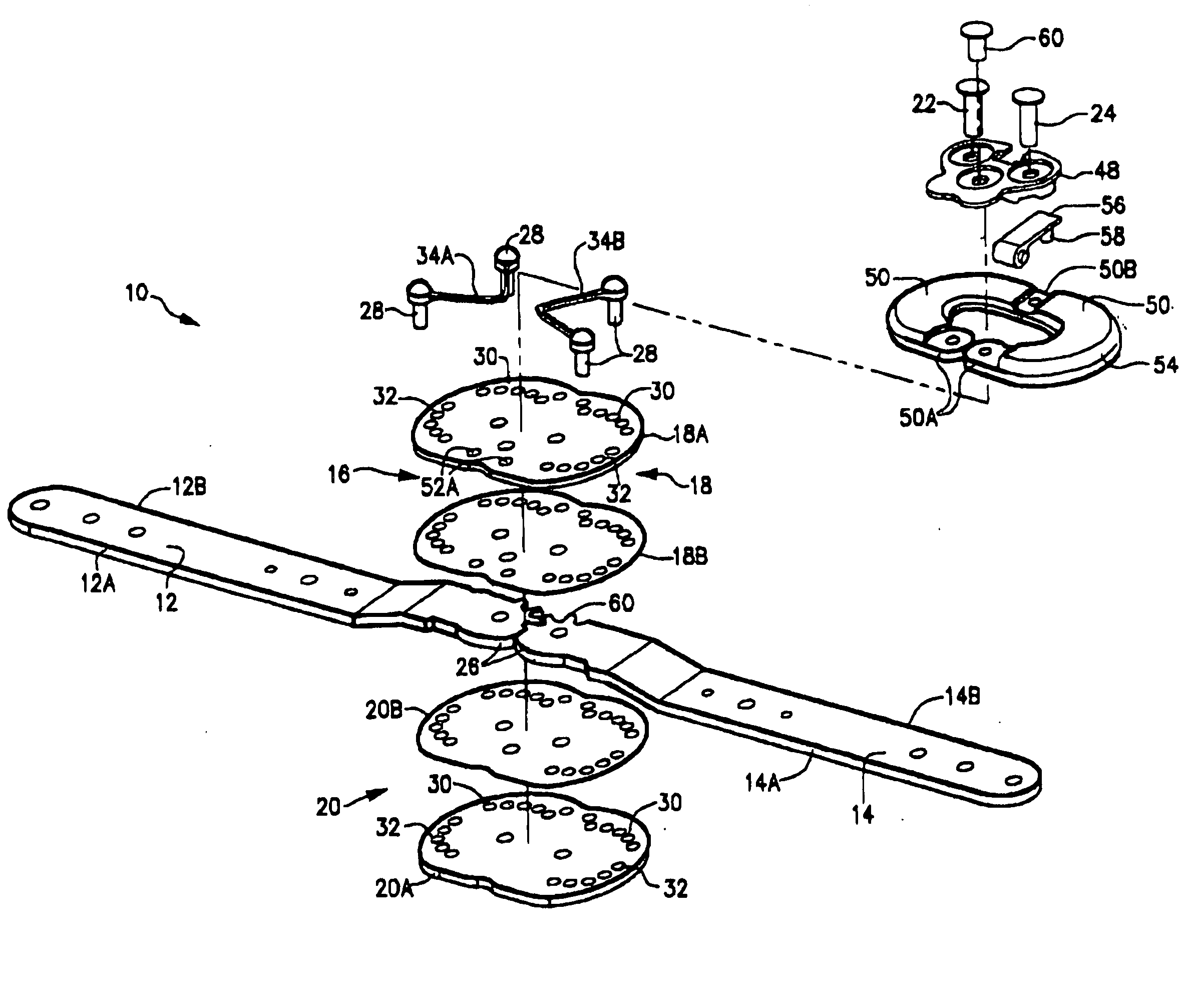
[0012] In accordance with the present invention, a cover for the limit pins is pivotally or swingably mounted on an axis perpendicular to the hinge plate, rather than on an axis parallel to the hinge plate as with the prior flip-top cap, so that the cover is not prone to being dislodged upon impact in a contact sport or otherwise.
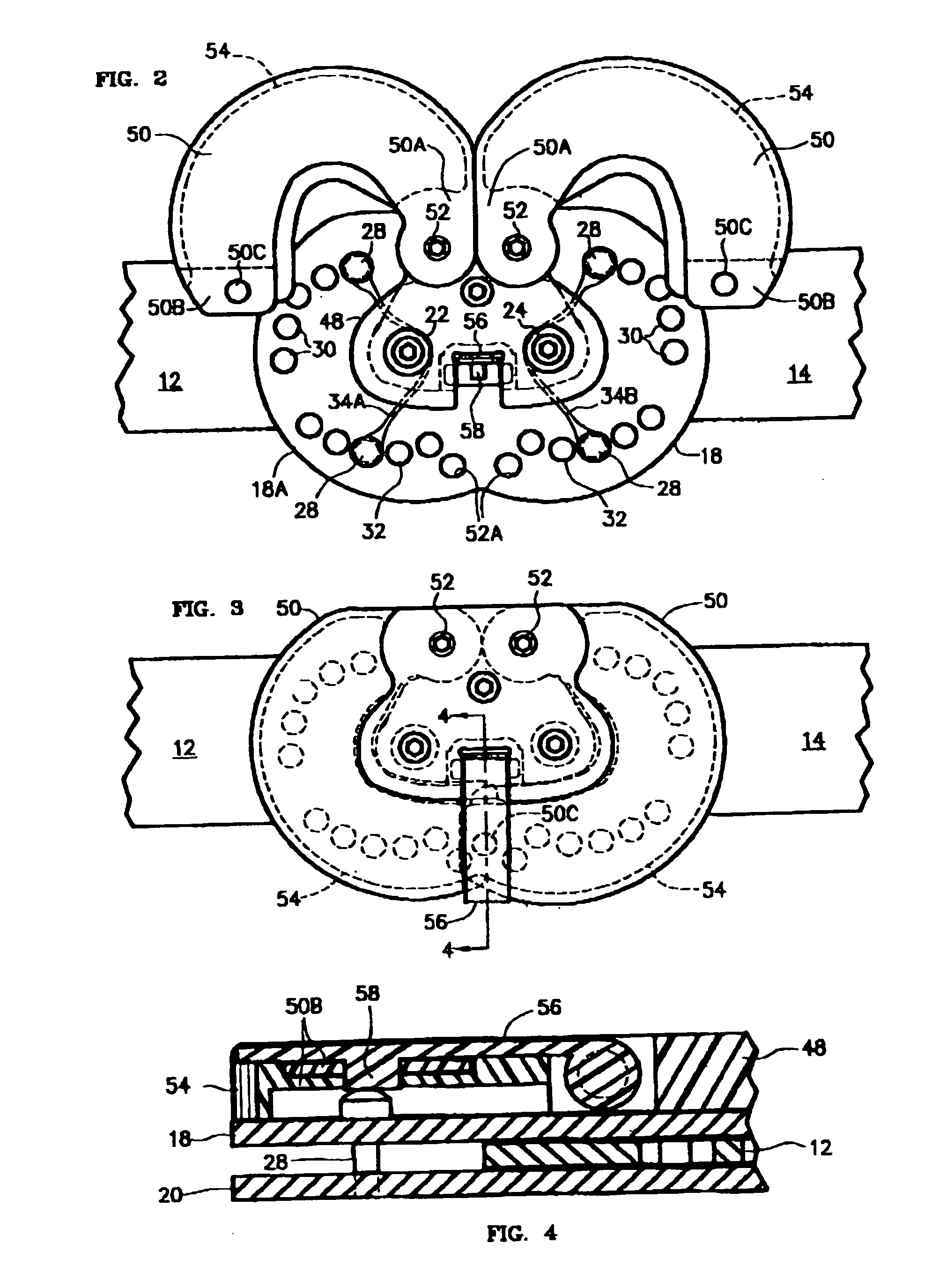
[0013] More particularly, in a preferred embodiment of the invention, the cover is comprised of two cover elements swingably mounted on a pivot axis or pivot axes normal to the plane of the hinge plate and moveable toward and away from one another, somewhat like a clam shell, to selectively cover and uncover the limit pins without being prone to inadvertent or accidental uncovering of the pins.
[0014] To further secure the cover or cover elements in closed or pin covering position, and to prevent inadvertent or accidental movement of the cover or cover elements to open position, a locking latch is incorporated in the cover assembly.

Problems solved by technology

The flip top cap or cover for the limit pins, unfortunately, is not particularly secure and is prone to popping open, particularly during contact sports, thereby openly exposing the limit pins and permitting the pins to be inadvertently disassociated from their respective apertures, whereupon the hinge is incapable of achieving its intended purpose (unless intended for complete flexion and complete extension).
The hinge, until reset, fails its purpose, during which time the knee intended to be protected could suffer further trauma.

Method used


Image

  • Orthopedic polycentric hinge
  • Orthopedic polycentric hinge
  • Orthopedic polycentric hinge

Examples


Embodiment Construction

[0022] The following is a detailed description of an embodiment of the invention presently contemplated by the inventors to be the best mode of carrying out their invention. Except for the limit pin cover and retainers, the structure of the hinge is essentially the same as that of U.S. Pat. No. 5,443,444, which is incorporated herein by reference and to which reference is made for a more detailed disclosure of the hinge.

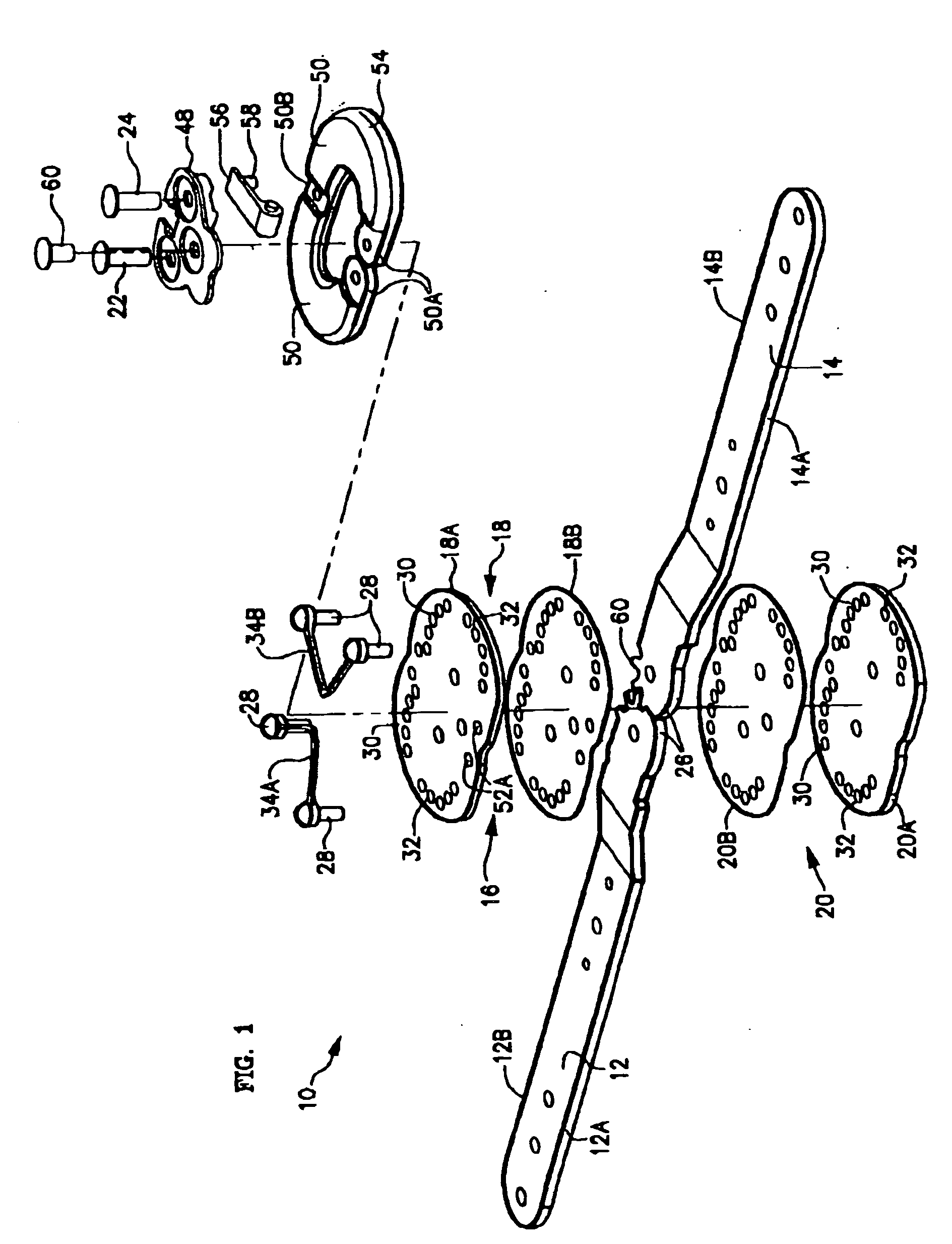
[0023] Referring to the drawings, an orthopedic polycentric hinge 10 is comprised of a pair of rigid support arms 12, 14 juxtaposed to one another at adjacent or proximal ends and which, in relation to the knee of the patient, have forwardly facing edges 12a, 14a and rearwardly facing edges 12b, 14b. The two support arms 12, 14 are pivotally interconnected at their proximal ends by a hinge assembly 16, comprised preferably of a pair of parallel spaced apart rigid hinge plates 18, 20 overlying the opposite sides, i.e., the exterior and interior sides respectively, of...


PUM


Abstract

A hinge for orthopedic braces includes a pair of support arms, a pair of pivot pins and a hinge plate. The arms are coupled to the hinge plate through the pivot pins and are rotateable between an extension position and a flexion position. The hinge plate has a plurality of adjustment apertures for selective reception of an extension limit pin and a flexion limit pin to selectively restrain rotation of the arms beyond an extension limit and a flexion limit. The pins are retained on the hinge by flexible retainers and are individually positionable among the apertures to adjust the range of motion of the arms. A pair of cover elements pivotally moveable in a plane parallel to the hinge plate provide an open position accommodating access to the pins and a closed position preventing inadvertent displacement of the pins from the apertures

Description

FIELD OF THE INVENTION [0001] The present invention relates to an orthopedic articulating brace, and more particularly, to an orthopedic polycentric hinge for knee braces having rigid relatively moveable support arms and means for conveniently adjusting the range of motion permitted between the arms. BACKGROUND [0002] The present invention constitutes an improvement on the polycentric hinge disclosed in U.S. Pat. No. 5,443,444, issued Aug. 22, 1995. [0003] As described in said patent, the human knee joint provides for relative articulation of the upper and lower legs, between the femur and tibia, through a plurality of centers or axes over an arc of about 180°. To effectively duplicate the movement of the human knee joint when necessary to mechanically assist the knee, for example, following injury or a surgical procedure, the art has developed articulated knee supporting braces embodying plural axis or polycentric hinges worn about the knee of the patient. These hinges may be used ...

Claims


Application Information

Patent Timeline
IPC IPC(8): A61F5/00
CPCA61F5/0123A61F2005/0167A61F2005/0139A61F2005/0134
Inventor POPP, WILLIAM J.MCKASKLE, DENNIS
Owner LINEBERGER BRADLEY
Learn More