
DC-based data center power architecture

a data center and power architecture technology, applied in the field of power distribution systems, can solve the problems of significant waste of energy resources, drive up the cost of operating data centers, and culprits of power consumption, so as to achieve the effect of reducing monthly power costs, ensuring server reliability, and ensuring reliability

Active Publication Date: 2006-12-21
EYP MISSION CRITICAL +1
View PDF11 Cites 41 Cited by
  • Summary
  • Abstract
  • Description
  • Claims
  • Application Information

AI Technical Summary

Benefits of technology

The patent text explains that leading rack-mount and open blade servers can now be powered with more reliable DC power, which is more efficient than traditional AC power. By distributing redundant DC power to each server, the thermal load is shifted outside the server, increasing server reliability and reducing power costs.

Problems solved by technology

The technical problem described in this patent text relates to the challenges facing data centers due to increasing demand for processing capacity and higher reliability requirements. These challenges include meeting the needs for continuous operation, efficient cooling, proper power management, and effective control over available physical space. Another issue is related to the poor efficiency of current AC power systems used in data centers, resulting in wasted energy and excessive heat generation. To solve these problems, there is a need for a DC-based architecture to replace existing AC-based solutions.

Method used


Image

  • DC-based data center power architecture
  • DC-based data center power architecture
  • DC-based data center power architecture

Examples


Embodiment Construction

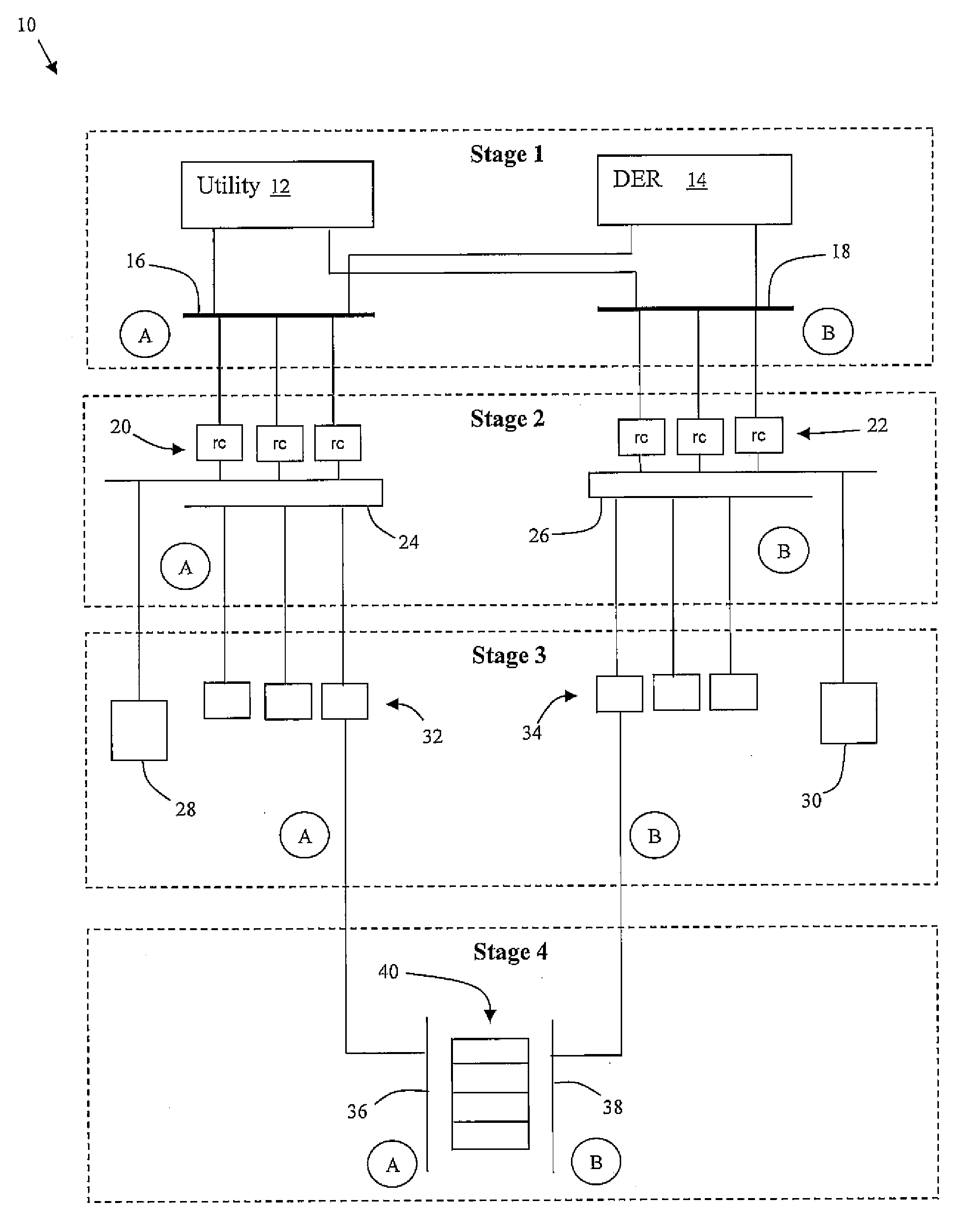
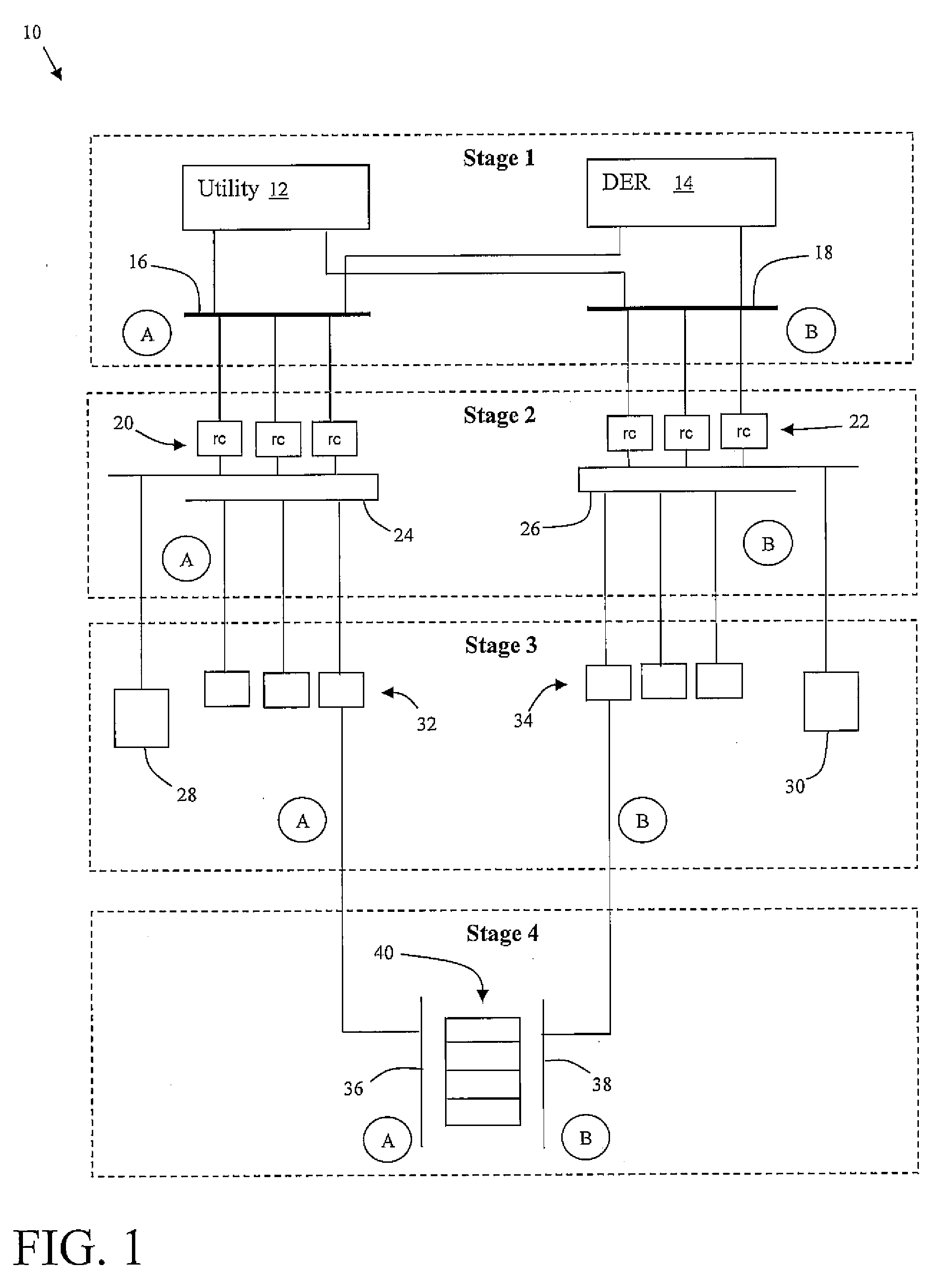
[0020] Referring now to drawings, FIG. 1 depicts an overview of an illustrative DC-based power distribution architecture 10 for powering critical loads 40 in a data center. Critical loads 40 are the main loads of a data center and include, for instance, equipment installed in cabinets (e.g., servers, computing components, etc.), on racks (e.g., telecom equipment such as routers and switches) or directly on the floor (e.g., heavy storage devices, etc.). Mechanical loads (not shown in FIG. 1) are related to HVAC systems, plumbing systems and various other essential loads supporting the critical loads 40. Note that for the purpose of this disclosure the term “data center” may refer to any facility that includes high density devices and / or other systems that run on DC, such as computer systems, servers, telecom equipment, medical equipment, etc.

[0021] Power distribution architecture 10 is shown broken down into four stages. In general, stage 1 provides an AC power distribution system t...


PUM


Abstract

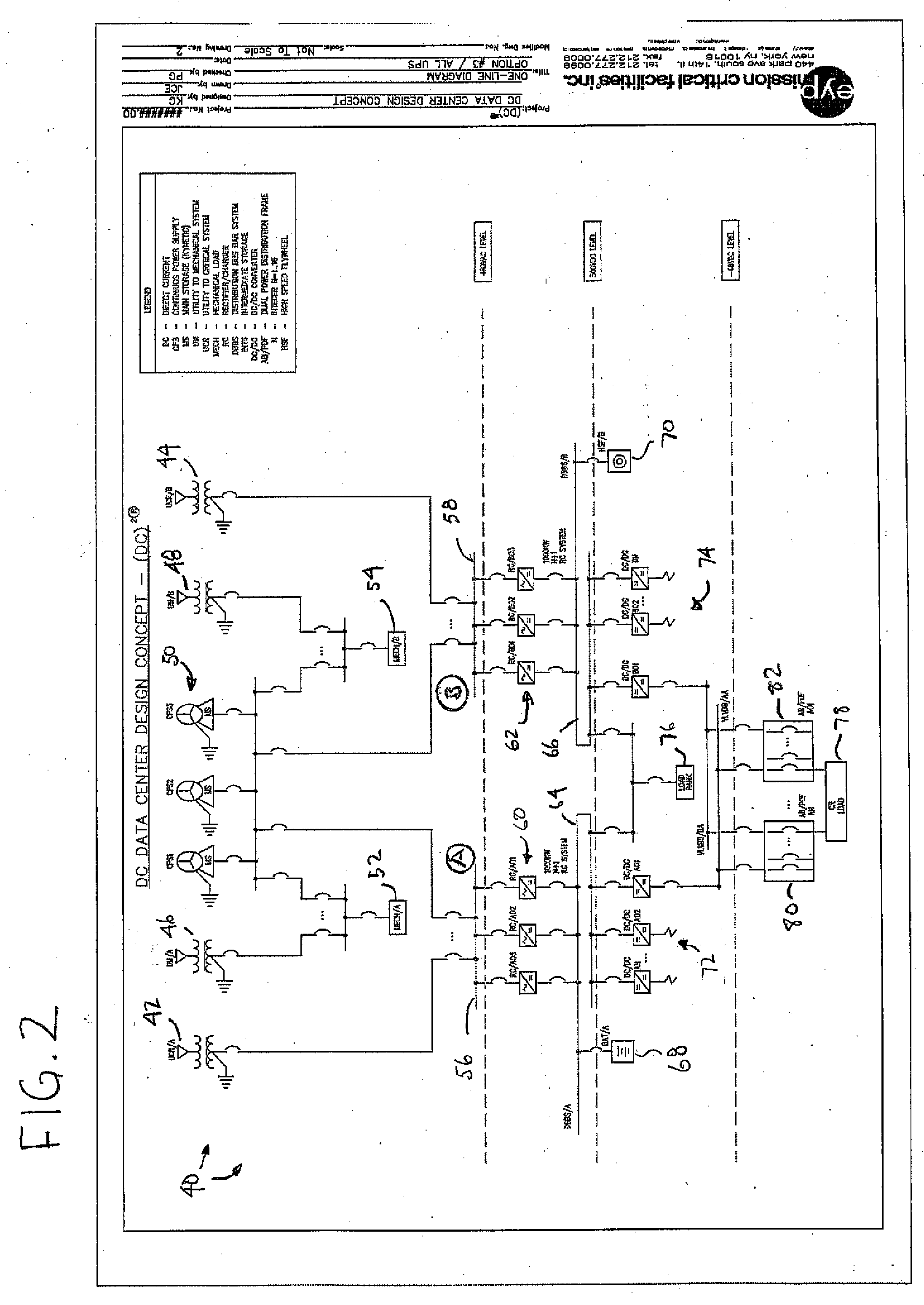
A DC-based power system including: an AC power distribution system for providing AC power to a first node and a second node; a first converting system coupled to the first node that converts AC power to DC power and outputs the DC power to a first distributed bus bar; a second converting system coupled to the second node that converts AC power to DC power and outputs the DC power to a second distributed bus bar; a first set of DC/DC converters that steps down the DC power from the first distributed bus bar to a first stepped down DC voltage; a second set of DC/DC converters that steps down the DC power from the second distributed bus bar to a second stepped down DC voltage; and a critical load distribution system that is powered by both the first stepped down DC voltage and the second stepped down DC voltage.

Description


Claims


Application Information

Patent Timeline
Owner EYP MISSION CRITICAL
Learn More