Eureka AIR delivers breakthrough ideas for toughest innovation challenges, trusted by R&D personnel around the world.

Bow sight with angled pins

a technology of sight pins and angled pins, which is applied in the field of sight pin construction of bow sights, can solve the problems of archers tending, difficult if not impossible, and the body of the sight pin itself becoming a distraction, and achieve the effect of preventing sound generation

Inactive Publication Date: 2006-12-21
AFSHARI ABBAS BEN
View PDF85 Cites 9 Cited by
  • Summary
  • Abstract
  • Description
  • Claims
  • Application Information

AI Technical Summary

Benefits of technology

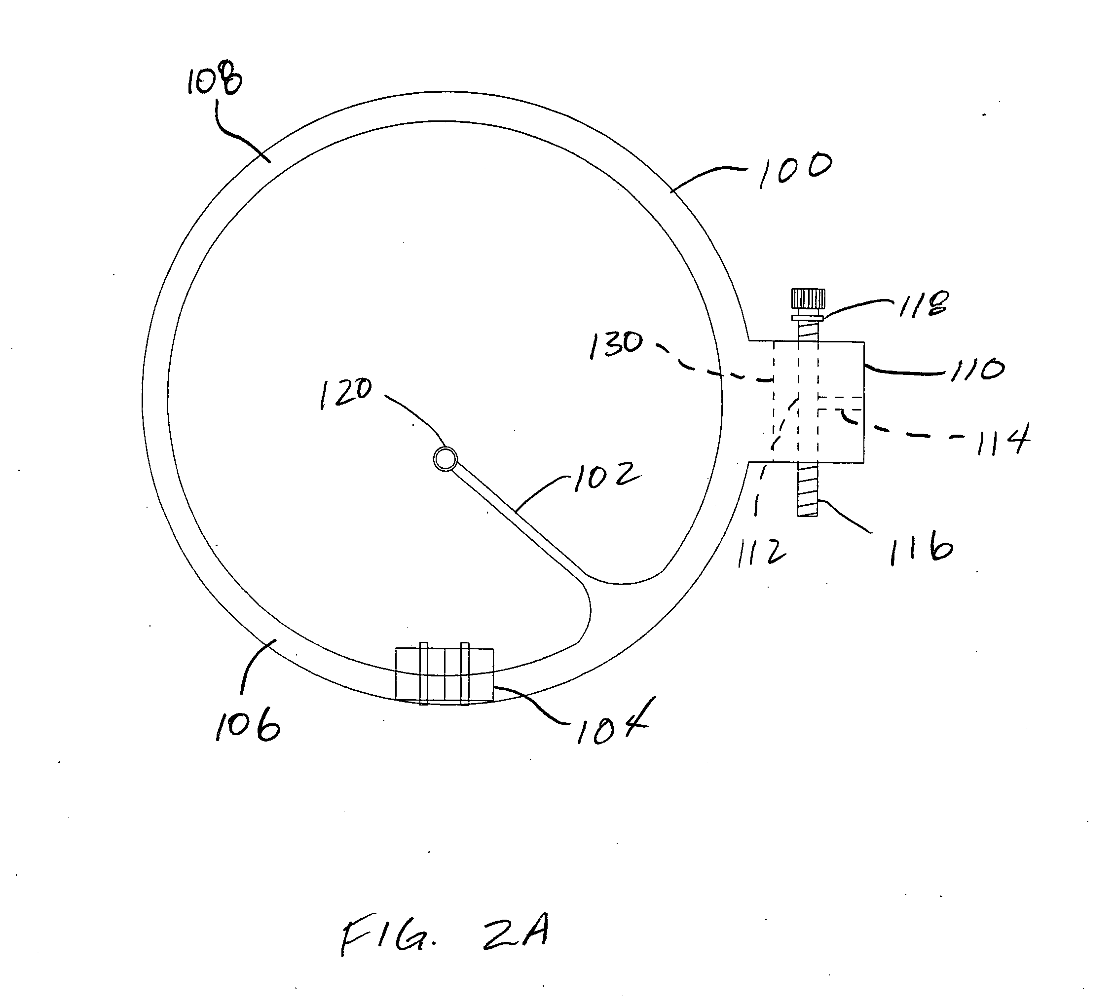
[0018] Each support structure is configured for attachment to and adjustment bracket that allows for individual vertical adjustment of each support structure. Because the sight pins are fixedly attached to their respective support structures, adjustment of the sight pins themselves is eliminated.
[0025] In still another embodiment, a dampening material is disposed between each of the stacked support structures to prevent sound generation between adjacent rings that may be caused by vibrations in the bow while shooting.

Problems solved by technology

Because of the relative size of such sight pins, however, accurate adjustment of the height of such pins is difficult if not impossible.
While reducing the obstruction of view by reducing the overall surface area of the pins that are visible to the archer, one of the drawbacks of this type of pin arrangement is that visually, the archer tends to focus on the entire length of the sight pin rather on the sigh point alone.
That is, because the sight pins are vertically arranged, the body of the sight pin itself often becomes a distraction when aiming.

Method used


Image

  • Bow sight with angled pins
  • Bow sight with angled pins
  • Bow sight with angled pins

Examples


Embodiment Construction

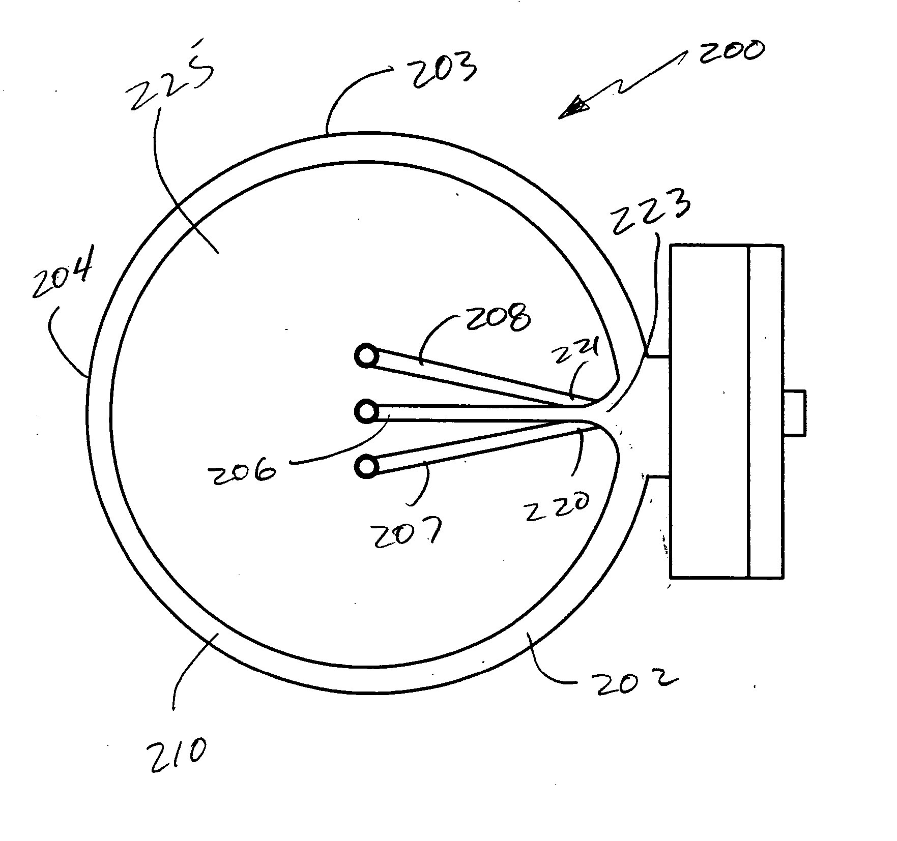
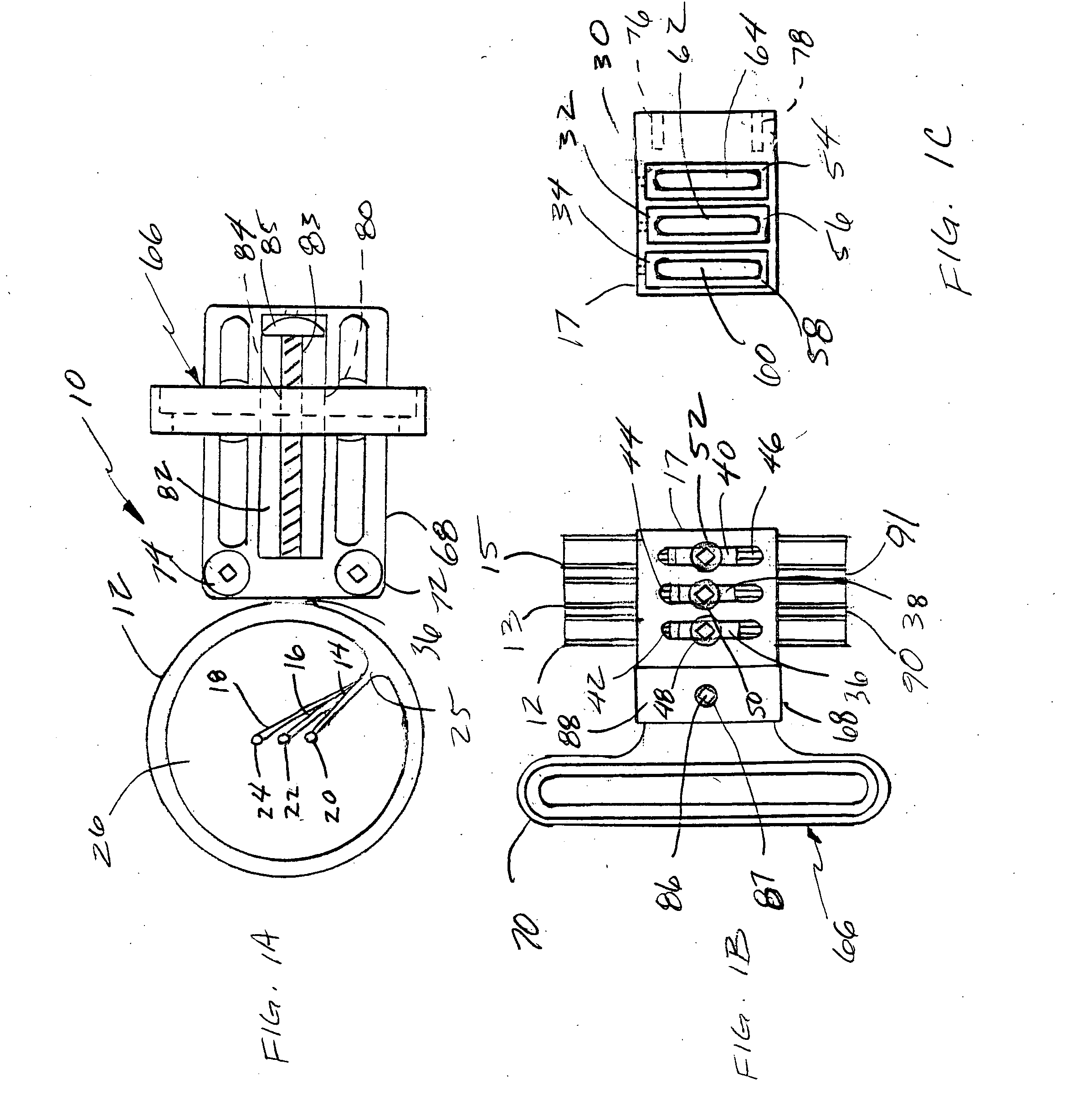
[0041]FIG. 1A illustrates a multiple pin bow sight, generally indicated at 10 in accordance with the principles of the present invention. The sight 10 is comprised of a plurality of support structures (only one of which is visible) 12 or rings which define pin guards, each of which support a sight pin 14, 16 and 18. Each sight pin 14, 16, and 18 is provided with sighting indicia or a sight tip 20, 22 and 24, respectively. The sight pins 14, 16 and 18 are angularly oriented when viewed by an archer in a shooting position as shown in FIG. 1A. That is, while at least a portion of each sight pin 14, 16 and 18 is visible, the base portions 25 of each sight pin 14, 16 and 18 are aligned when viewed as shown in FIG. 1A. Thus, each of the sight pins 16 and 18 are positioned behind the sight pin 14, with the base of each sight pin 14, 16 and 18 originating from substantially the same visual point and the sight tips 20, 22 and 24 being vertically aligned while being vertically spaced with the...


PUM


Abstract

A bow sight is comprised of at least two support structures, at least one of the support structures supporting at least one angled sight pin. Each support structure is adjustably attached to a mounting member that allows individual vertical adjustment of each support structure and thus individual vertical adjustment of each sight point of the sight pins.

Description

CROSS-REFERENCE TO RELATED APPLICATIONS [0001] This application is a continuation-in-part of and claims priority to U.S. patent application Ser. No. 11 / 079,004 now pending, which is a continuation of U.S. patent application Ser. No. 10 / 435,943, which was a continuation-in-part of U.S. patent application Ser. No. 09 / 989,935, now U.S. Pat. No. 6,560,884, which was a continuation-in-part of U.S. patent application Ser. No. 09 / 991,243, now U.S. Pat. No. 6,725,854. [0002] Ser. No. 09 / 989,935, now U.S. Pat. No. 6,560,884 and U.S. patent application Ser. No. 09 / 991,243.BACKGROUND OF THE INVENTION [0003] 1. Field of the Invention [0004] This invention relates generally to sights for archery bows and, more specifically, to bow sights having sight pin constructions that are angularly oriented. [0005] 2. Description of the Art [0006] Archery bow sights utilizing a plurality of sight pins have been known in the art for many years. Typically, these sights use a bracket or other mounting structur...

Claims


Application Information

Patent Timeline
Patent Type & Authority Applications(United States)
IPC IPC(8): F41G1/467
CPCF41G1/467
Inventor AFSHARI, ABBAS BEN
Owner AFSHARI ABBAS BEN
Why Eureka
Eureka Blog
Learn More