
Shaving implement having a cap forward pivot

Inactive Publication Date: 2006-12-21
EDGEWELL PERSONAL CARE BRANDS LLC
View PDF8 Cites 68 Cited by
  • Summary
  • Abstract
  • Description
  • Claims
  • Application Information

AI Technical Summary

Benefits of technology

[0010] Another advantage of the present invention is that the forces that act on the razor cartridge that occur during normal shaving that tend to cause the razor cartridge to pivot relative to the handle are reduced. The biasing member, in conjunction with the connection of the razor cartridge to the handle via the bridge, allows erratic forces to be buffered, which facilitates the steady positioning of the razor cartridge relative to the surface being shaved.
[0011] Still another advantage of the present invention is that the flexibility of the supporting arms at which the razor cartridge is mounted provide shock absorbing qualities to the shaving implements during a shaving operation. The degree of flexibility of the supporting arms effectively eliminates or reduces the amount of chatter (uncontrolled rapid alternation between two positions) experienced by the razor blades during the shaving operation.

Problems solved by technology

In these types of razors, the razor cartridge tends to pivot erratically when used in an effort to precisely control movement for trimming intricate details in a hirsute surface.
One cause of the erratic movement is the exertion of minute and unintentional forces on the handle.
Another cause is generally due to frictional forces caused by the surface being shaved passing over the guard bar.
Still another cause may be that forces encountered during the cutting of the hair tend to urge the razor cartridge to the rotated position.
The problem is exacerbated when the user is shaving or trimming intricate details.
Consequently, the razor cartridge, experiencing greater forces on the guard and the razor blades, tends to rotate away from the surface being shaved, thereby causing the razor blades to lose contact.
The result is that, even with precise attention and the presence of a guard bar, the desired shave is not achieved because the razor blades are not in the intended position (in contact with the surface being shaved).

Method used


Image

  • Shaving implement having a cap forward pivot
  • Shaving implement having a cap forward pivot
  • Shaving implement having a cap forward pivot

Examples


Embodiment Construction

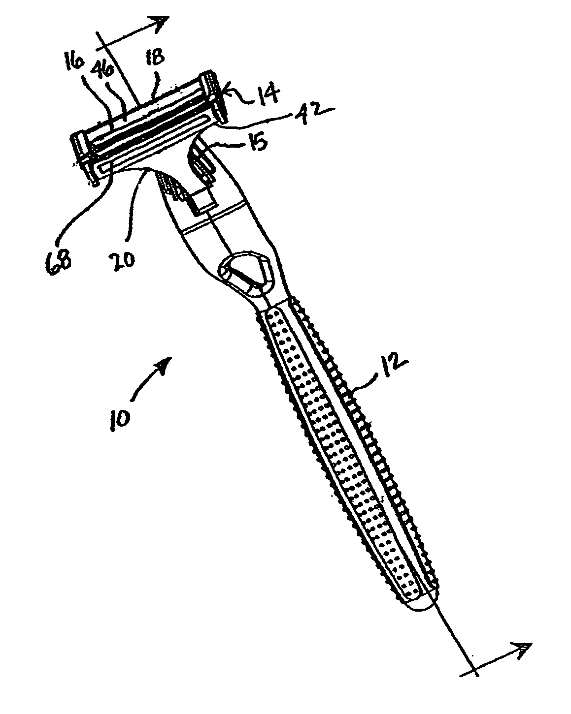
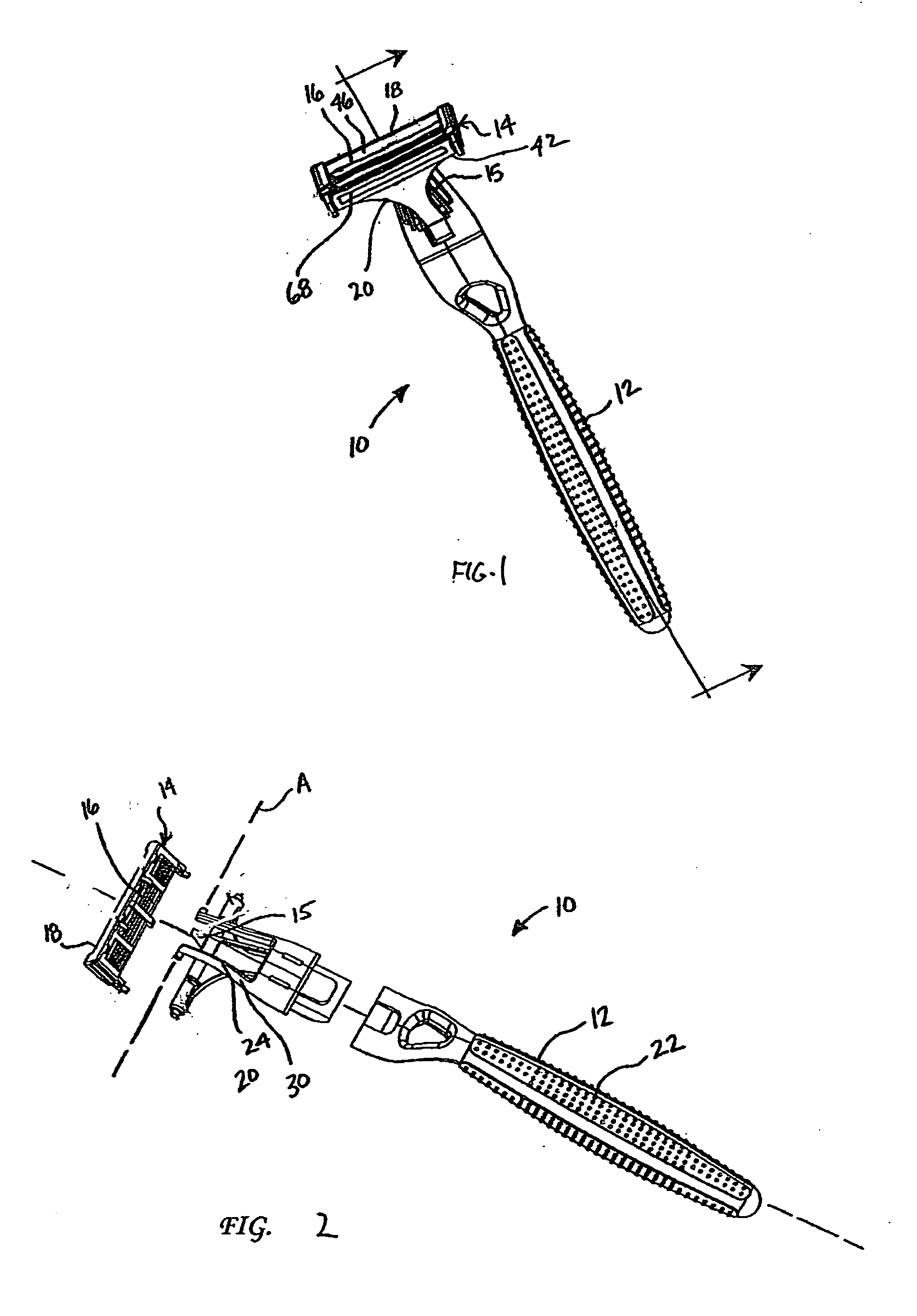
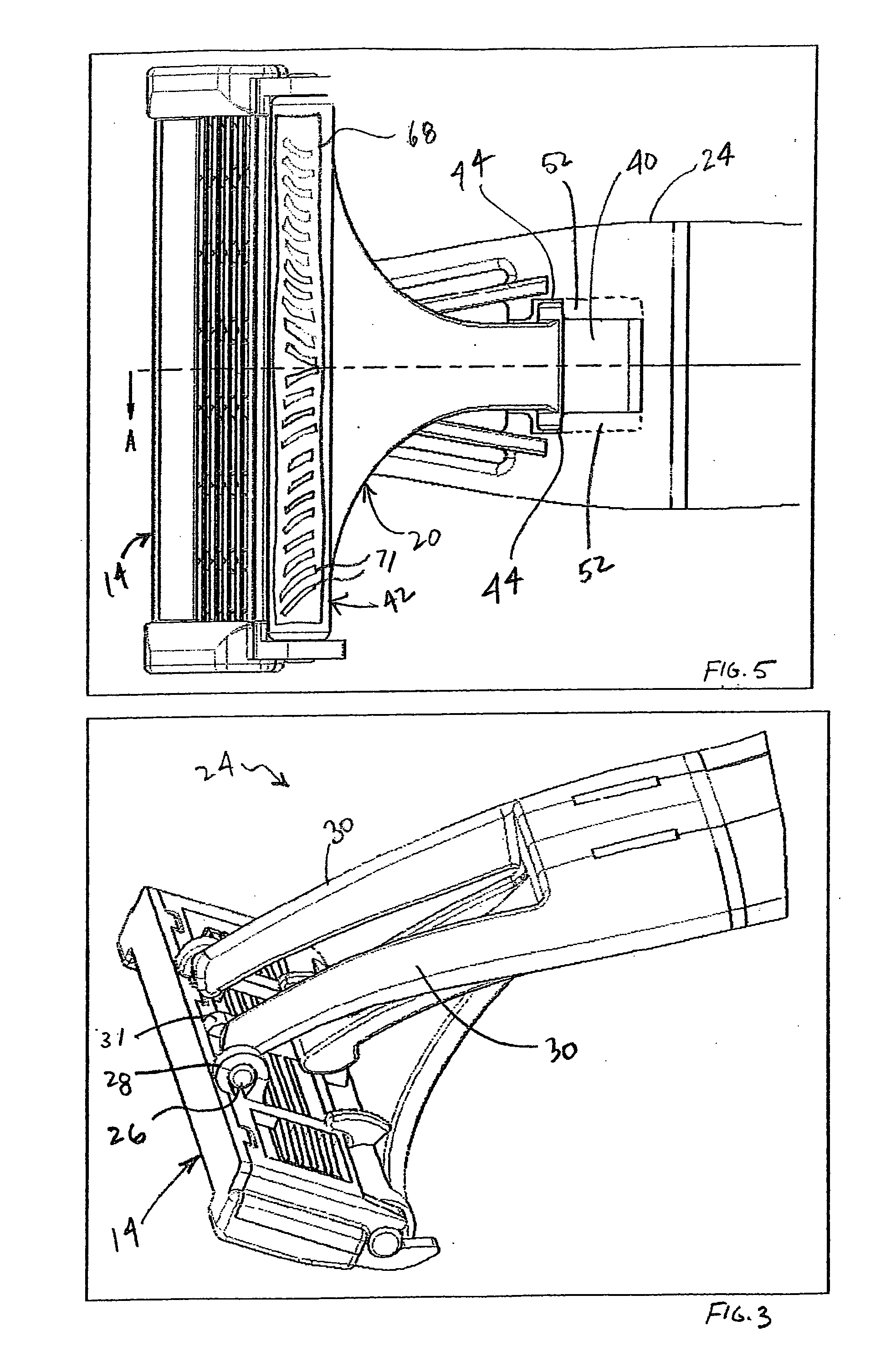
[0021] Referring to FIG. 1, a shaving implement of the present invention is depicted generally by the reference numeral 10. The shaving implement 10 (which may be a wet shaving razor) includes a handle 12 and a razor cartridge 14 pivotally attached to the handle. The razor cartridge 14 includes at least one razor blade 16 (two are shown) and a cap 18 positioned aft of the razor blades. A bridge 20 is pivotally connected to a forward portion of the razor cartridge 14 in front of the razor blades 16 and extends to the handle 12. A portion of the bridge 20 adjacent the pivotal connection of the bridge to the razor cartridge 14 defines a guard 42.

[0022] The cap 18 may include an attached comfort strip 46 (also known as a lubricating strip), which may include a shaving aid. For example, the shaving aid may include one or more of the following:

[0023] A. A lubricating agent for reducing the frictional forces between the razor and the skin, e.g., a micro-encapsulated silicone oil.

[0024] B...


PUM


Abstract

A shaving implement includes a handle; a razor cartridge pivotally connected thereto; a biasing member extending from the handle and contacting the razor cartridge; and a bridge pivotally connected to the razor cartridge and slidably connected to the handle. The razor cartridge includes one or more razor blades and a cap located aft of the blades. The razor cartridge is pivotally connected to the handle such that the cartridge pivots about an axis that is generally parallel to and aft of the razor blades, the cartridge being pivotable between a neutral position and a rotated position. The biasing member extending from the handle is in contact with the razor cartridge to urge the cartridge toward the neutral position. The bridge is slidable between a first position when the razor cartridge is in the neutral position and a second position when the cartridge is in the rotated position.

Description

TECHNICAL FIELD [0001] The present disclosure relates to shaving implements in general and, more particularly, to shaving implements having razor cartridges in which the razor cartridges pivot about axes located below the caps of the razor cartridges. BACKGROUND OF THE INVENTION [0002] Shaving implements, typically those known as wet shave razors, generally each include a razor cartridge and a handle. The razor cartridge includes at least one razor blade mounted therein aft of a guard and forward of a cap such that cutting edges of the razor blade are at or proximate a shave plane defined as a theoretical plane extending tangentially from the uppermost portions of the guard and the cap. The razor cartridge is pivotally mounted on the handle such that during use the razor cartridge is able to pivot relative to the handle between a neutral position and a rotated position. The pivoting action of the razor cartridge between the neutral and rotated positions relative to the handle enable...

Claims


Application Information

Patent Timeline
IPC IPC(8): B26B21/52
CPCB26B21/225
Inventor FOLLO, THOMAS A.RICHARD, PAUL D.PACILIO, JOHN F.
Owner EDGEWELL PERSONAL CARE BRANDS LLC
Learn More