
Warpage angle measurement apparatus and warpage angle measurement method for optical recording medium

Inactive Publication Date: 2006-12-14
TDK CORPARATION
View PDF5 Cites 11 Cited by
  • Summary
  • Abstract
  • Description
  • Claims
  • Application Information

AI Technical Summary

Benefits of technology

[0013] In view of the foregoing problems, various exemplary embodiments of this invention provide a warpage angle measurement apparatus and a warpage angle measurement method for an optical recording medium, which can measure an angle of warpage of an optical disc and a cartridge for the optical disc that is caused by a rapid temperature change or a rapid humidity change in a short time.
[0015] The object to be measured may be accommodated in one constant temperature chamber and the environmental condition may be rapidly changed. Alternatively, two constant temperature chambers may be used and environmental conditions inside those constant temperature chambers may be set to be different from each other. In this case, when the object to be measured is first placed in one of the two constant temperature chambers and is then carried into the other constant temperature chamber, it is possible to rapidly change the environmental condition of the optical disc in a short time and measure the angle of warpage of the object to be measured.

Problems solved by technology

On the other hand, as the wavelength of the laser light is shorter and the numerical aperture of the objective lens is larger, there is a tendency that coma aberration is generated and reduces accuracy of recording and reproducing information.
This type of optical disc has high recording density and therefore the accuracy of recording and reproducing information is easily affected by dust, scar, or the like.
Thus, there is a tendency that warpage causes interference between the optical disc and the objective lens more easily in this type of optical disc than in the conventional optical disc, even if the degree of the warpage is the same.
Therefore, this type of optical disc has a problem that warpage can easily occur with a rapid change in a temperature or a humidity.
For example, when an optical disc that is placed in an outdoor location in winter and is therefore cooled down to a temperature close to an outside air temperature is mounted on a video camera or the like that is heated by being turned on, an environmental temperature of the optical disc increases by several tens of degrees C. in several seconds and warpage may occur.
Moreover, when an optical disc that is placed in an outdoor location in summer and is therefore heated to a temperature close to an outside air temperature is mounted on a recording and reproduction device or the like that is placed and cooled in an air-conditioned room, an environmental temperature of the optical disc lowers by several tens of degrees C. in several seconds and warpage may occur.
Large warpage can easily cause an error in reading and reproduction of information.
However, even in the case where the warpage of the optical disc only is suppressed within the predetermined limit value, when that optical disc is mounted in the cartridge, warpage exceeding the predetermined limit value may occur in the optical disc in the cartridge or warpage of the cartridge may occur.
That warpage may cause an error in reading and reproduction of information.
However, in the conventional optical disc such as CD and DVD, the numerical aperture of the objective lens is small and there is a sufficient distance between the optical disc and the objective lens.
Therefore, there is no method for measuring an angle of warpage of an optical recording medium caused by a rapid temperature change or a rapid humidity change occurring in a short time.
Moreover, there is no method for measuring an angle of warpage of an optical disc while the optical disc is mounted in a cartridge.

Method used


Image

  • Warpage angle measurement apparatus and warpage angle measurement method for optical recording medium
  • Warpage angle measurement apparatus and warpage angle measurement method for optical recording medium
  • Warpage angle measurement apparatus and warpage angle measurement method for optical recording medium

Examples


Embodiment Construction

[0039] Preferred exemplary embodiments of the present invention will now be described in detail, with reference to the drawings.

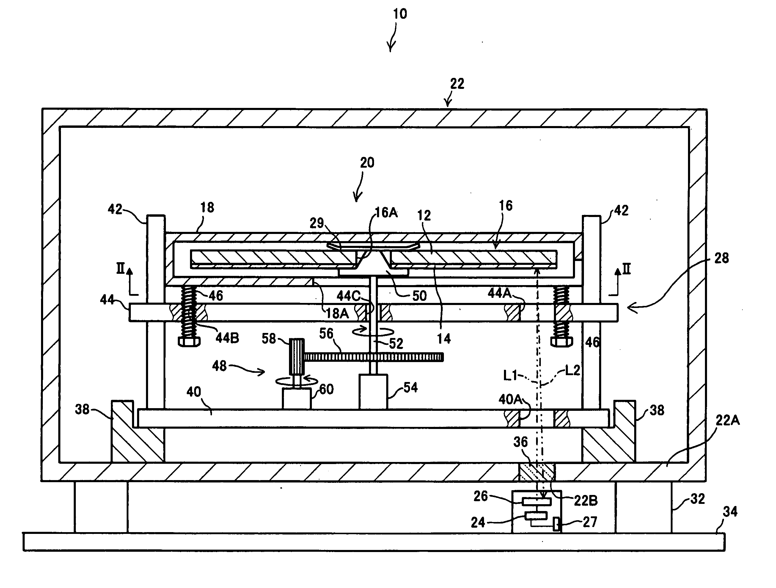
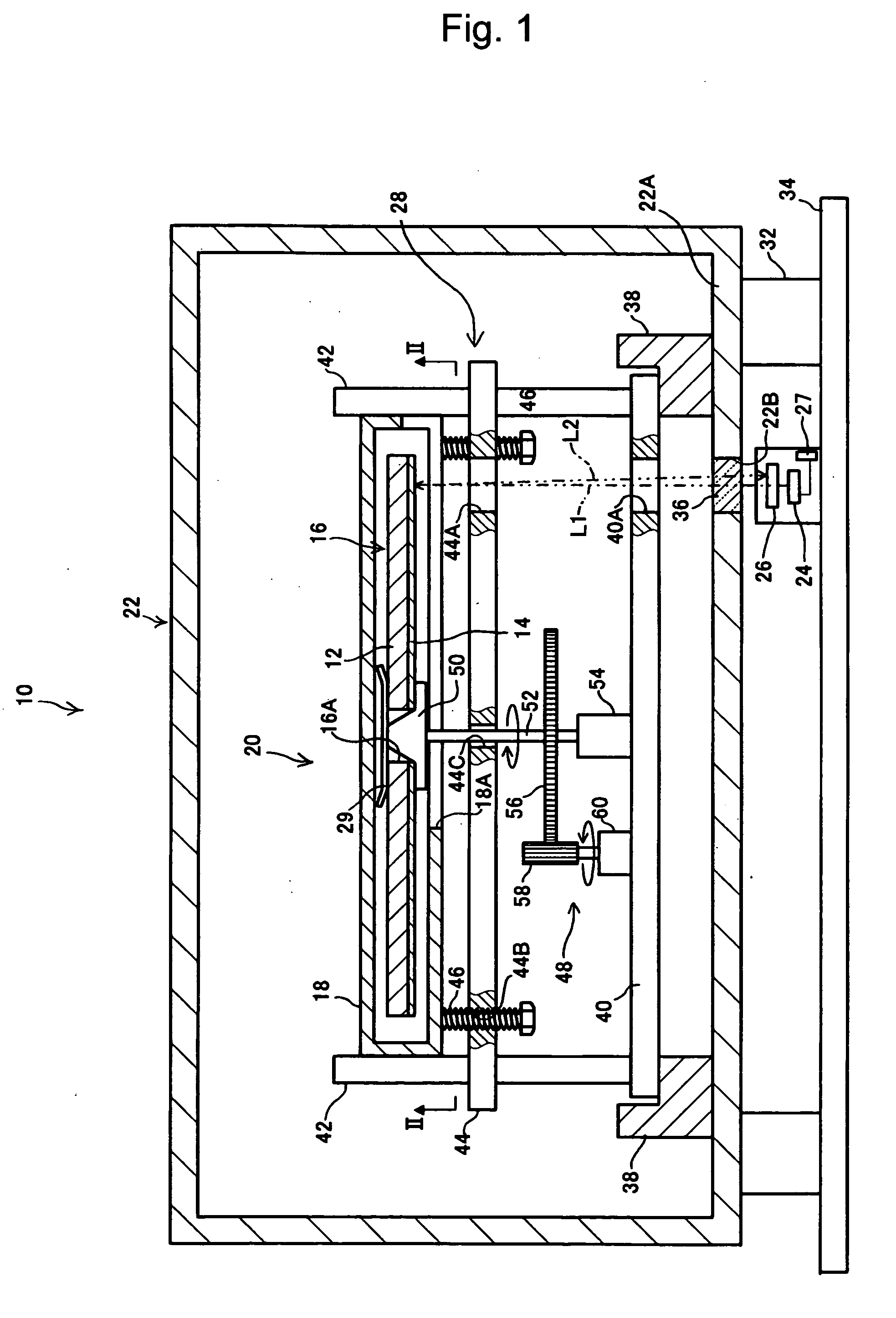
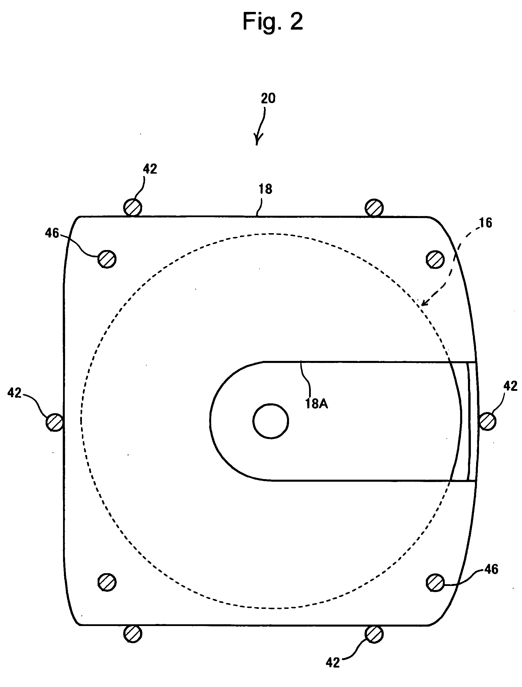
[0040] As shown in FIG. 1, a warpage angle measurement apparatus 10 includes: a constant temperature chamber 22 for accommodating an optical recording medium 20 in which an optical disc 16 as an object to be measured, which has a light-transmitting layer 14 thinner than a substrate 12, is mounted in a cartridge 18 so as to adjust the surrounding of the optical recording medium 20 to have a predetermined environmental condition; a laser transmitter 24 for causing laser oscillation to emit laser light to the optical disc 16; and a light-receiving unit 26 for receiving the laser light reflected from the optical disc 16 and detecting a relative angle of an optical path L2 of the reflected laser light with respect to an optical path L1 of the emitted laser light.

[0041] The warpage angle measurement apparatus 10 also includes an arithmetic unit 27 for calculati...


PUM


Abstract

A warpage angle measurement apparatus and a warpage angle measurement method are provided that can measure an angle of warpage of an optical disc and a cartridge for the optical disc caused by a rapid environmental change such as a temperature change or a humidity change in a short time. The warpage angle measurement apparatus 10 includes: a constant temperature chamber 22 for accommodating an optical recording medium 20 formed by mounting the optical disc 16 as an object to be measured in the cartridge 18 and for adjusting a surrounding of the optical recording medium 20 to have a predetermined environmental condition; a laser oscillator 24 for causing laser oscillation to emit laser light to the optical disc 16; and a light-receiving unit 26 for receiving the laser light reflected from the optical disc 16 and detecting a relative angle of an optical path L2 of the reflected laser light with respect to an optical path L1 of the emitted laser light.

Description

TECHNICAL FIELD [0001] The present invention relates to a warpage angle measurement apparatus and a warpage angle measurement method for measuring an angle of warpage of an optical disc and a cartridge for the optical disc. BACKGROUND ART [0002] Shortening of the wavelength of laser light and increasing of the numerical aperture NA of an objective lens can increase recording density and recording capacity in an optical disc. On the other hand, as the wavelength of the laser light is shorter and the numerical aperture of the objective lens is larger, there is a tendency that coma aberration is generated and reduces accuracy of recording and reproducing information. However, margin for tilt (warpage) of the optical disc can be ensured by making a light-transmitting layer of the optical disc thin, thus ensuring the accuracy of recording and reproducing information. [0003] In recent years, an optical disc has attracted attention, in which blue-violet laser light having a wavelength as s...

Claims


Application Information

Patent Timeline
IPC IPC(8): G11B7/00G11B7/095G01B11/26G11B7/26G11B23/113
CPCG11B7/268G11B7/0956
Inventor YAMADA, TAKASHIKOMAKI, TSUYOSHI
Owner TDK CORPARATION
Learn More