Array antenna calibration apparatus and method
a technology of array antennas and calibration methods, applied in electrical devices, instruments, antennas, etc., can solve the problems of limited channel capacity and inability to correctly control beam patterns, and achieve accurate results, reduce manufacturing costs, and ensure the interval-dependent calibration of antenna elements
- Summary
- Abstract
- Description
- Claims
- Application Information
AI Technical Summary
Benefits of technology
Problems solved by technology
Method used
Image
Examples
first embodiment
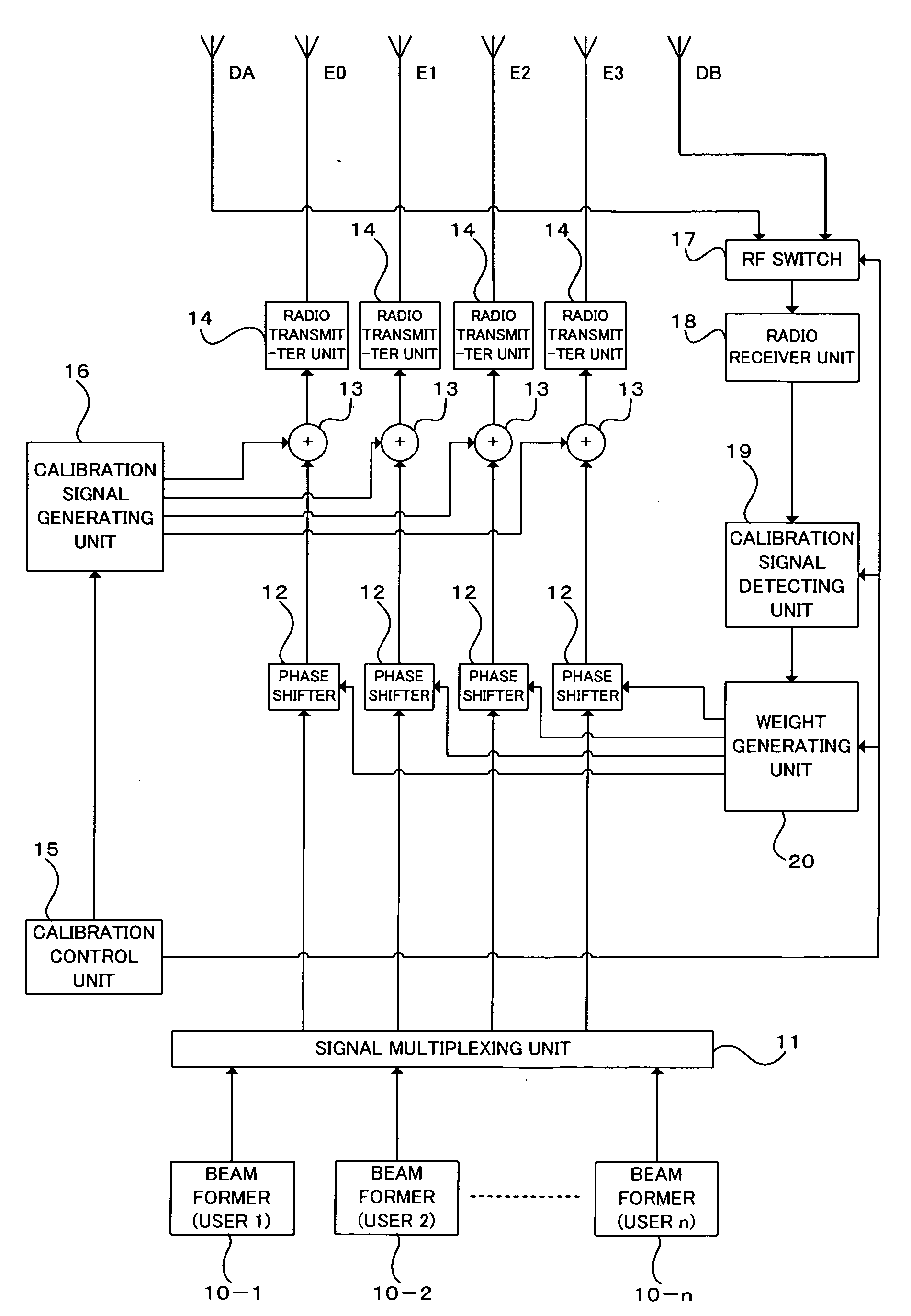
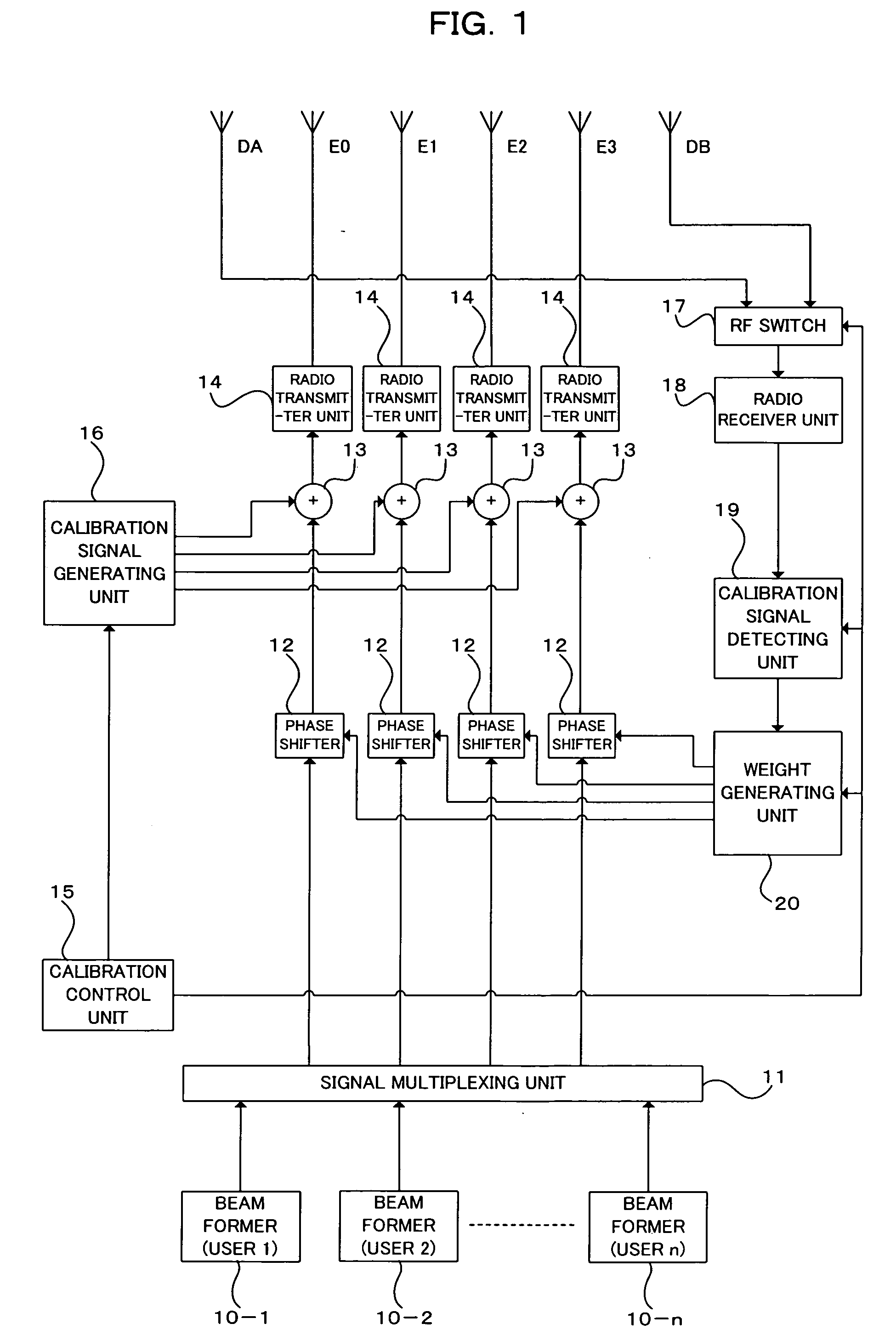
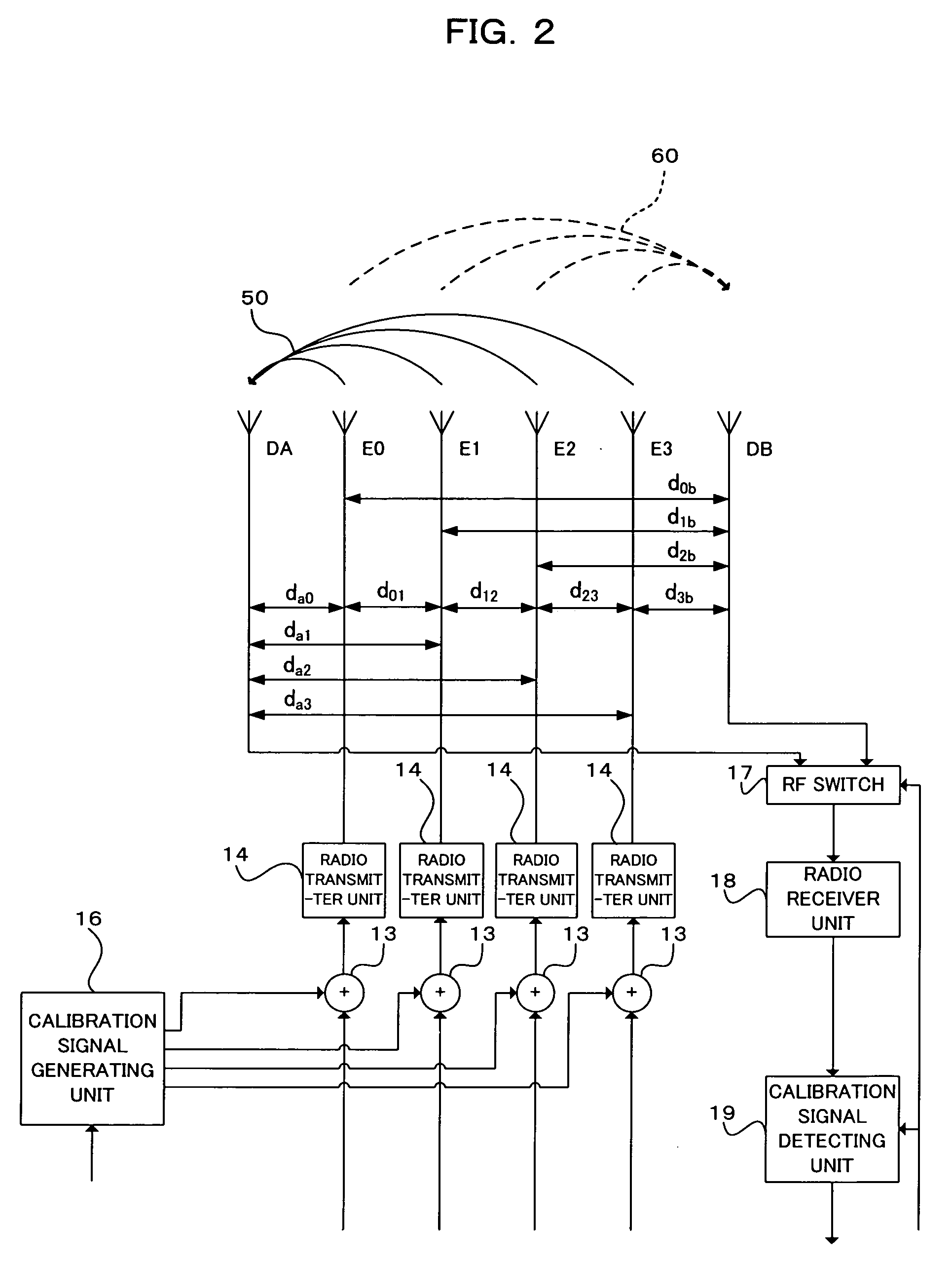
[0036]FIG. 1 is a block diagram showing a construction (for downlink) of a radio transmitter to which an array antenna calibration apparatus of a first embodiment of the present invention is applied. The radio transmitter of FIG. 1 includes: antenna elements E0, E1, E2, E3, DA, and DB (in FIG. 1, a total of six antenna elements) constituting a linear array antenna; beam formers 10-1 through 10-n (n is an integer not smaller than 2) for multiple users; a signal multiplexing unit 11; phase shifters 12, adders 13, and radio transmitter units 14 provided, one for each of the antenna elements E0, E1, E2, and E3; a calibration control unit 15; a calibration signal generating unit 16; an RF switch 17; a radio receiver unit 18; a calibration signal detecting unit 19; a weight generating unit 20. Antenna elements DA and DB disposed, one on each side of the linear array antenna, are dummy antennas for shaping emission patterns from the antenna elements E0, E1, E2, and E3. Note that the number...
second embodiment
[2] Second Embodiment
[0060]FIG. 3 is a block diagram showing a construction (for uplink) of a radio receiver to which an array antenna calibration apparatus of a second embodiment of the present invention is applied. The radio receiver of FIG. 3 includes: antenna elements E0, E1, E2, E3, DA, and DB (in FIG. 3, a total of six antenna elements) constituting a linear array antenna; radio receivers 31 and phase shifters 32 provided, one for each of the antenna elements E0, E1, E2, and E3; a signal demultiplexing unit 33; beam formers 34-1 through 34-n (n is an integer not smaller than 2) for multiple users; a calibration control unit 35; a calibration signal generating unit 36; a radio transmitter unit 37; an RF switch 38; a calibration signal detecting unit 39; and a weight generating unit 40. In this example, also, antenna elements DA and DB, disposed one on each side of the linear array antenna, are dummy antennas for shaping emission patterns from the antenna elements E0, E1, E2, an...
third embodiment
[3] Third Embodiment
[0078]FIG. 5 is a block diagram showing a construction (for downlink) of a radio transmitter to which an array antenna calibration apparatus of a third embodiment of the present invention is applied. The radio transmitter of FIG. 5 differs from the construction of FIG. 1 in that radio receiver units 18A and 18B and calibration signal detecting units 19A and 19B are provided for the dummy antenna elements DA and DB, respectively, instead of the RF switch 17.
[0079] Here, the radio receiver units 18A and 18B per se have the same or the similar functions to those of the radio receiver unit 18 already described. The calibration signal detecting units 19A and 19B per se have functions the same as or similar to those of the calibration signal detecting unit 19 already described. That is, although the construction of FIG. 1 includes one radio receiver unit 18 and one calibration signal detecting unit 19 for common use between the dummy antenna elements DA and DB by a sw...
PUM
 Abstract
Description
Claims
Application Information
 - R&D
- Intellectual Property
- Life Sciences
- Materials
- Tech Scout
- Unparalleled Data Quality
- Higher Quality Content
- 60% Fewer Hallucinations
Browse by: Latest US Patents, China's latest patents, Technical Efficacy Thesaurus, Application Domain, Technology Topic, Popular Technical Reports.
© 2025 PatSnap. All rights reserved.Legal|Privacy policy|Modern Slavery Act Transparency Statement|Sitemap|About US| Contact US: help@patsnap.com


