
Selectable range lobes using wide-band array

a wide-band array and range lobe technology, applied in the field of unambiguous range resolution of radar systems, can solve problems such as difficult signal classification

Inactive Publication Date: 2006-12-07
TELEFON AB LM ERICSSON (PUBL)
View PDF37 Cites 3 Cited by
  • Summary
  • Abstract
  • Description
  • Claims
  • Application Information

AI Technical Summary

Benefits of technology

The patent describes a way to control the resolution of a radar system using an ultra-wide-band signal. This signal is generated and sent out by a special antenna, and then comes back to the system through an echo signal. By analyzing the power spectrum of the noise signal, the system can determine the range of the target being tracked. This technology can be used in both bistatic and monostatic configurations, and can improve the accuracy and efficiency of radar systems.

Problems solved by technology

Signal classification is difficult with present solutions and different hardware solutions have to be used for a respective function category, for instance, a radar function or a jamming function.

Method used


Image

  • Selectable range lobes using wide-band array
  • Selectable range lobes using wide-band array
  • Selectable range lobes using wide-band array

Examples


Embodiment Construction

[0014] In a typical illustrative embodiment a very broad-banded signal is generated. The generated signal may be continuous band-limited white or colored noise and transmitted by an antenna, which for instance is isotropic in its horizontal plane. Echo signals in a bistatic or monostatic configuration are received.

[0015] Each antenna may be a vertical array to increase the gain in the horizontal plane. To minimize leakage between the transmitting antenna and the receiver antennas the transmitting antenna preferably is positioned as far as possible from the receiving antennas and for instance at a different height.

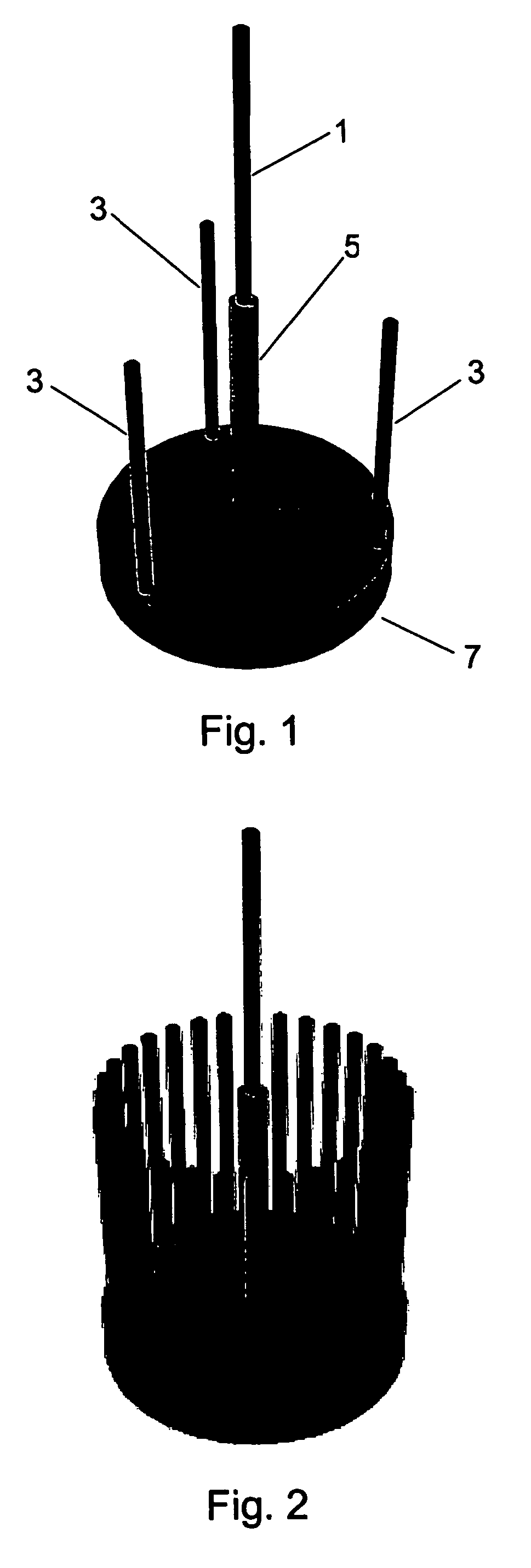
[0016]FIG. 1 illustrates a principal shape with n=3, the transmitting antenna is denoted as 1 and the receiver antennas are denoted 3. A structure carrying the transmitter antenna is denoted as reference number 5. A transmitter and n receivers with accompanying signal processing is housed in the electronic unit 7. FIG. 2 illustrates a practical embodiment of a circular ar...


PUM


Abstract

The present inventive concept for bistatic or monostatic radar utilization discloses a method and a system for unambiguous range resolution utilizing an ultra wide-band signal, generally a wide-band noise signal which may be continuous bandwidth limited white or colored noise. The noise signal is typically generated and radiated by a transmitting antenna covering the entire reception range of a receiving sparse antenna. An echo signal is received by the receiving antenna. By means of a selected auto-correlation function defining the wide-band noise signal power spectrum, the convolution of the radiated output signal and the received echo input signal will give the target range information.

Description

TECHNICAL FIELD [0001] The present invention relates to a method and system for unambiguous range resolution of a radar system. BACKGROUND [0002] In radar systems there is a desire to keep peak power as low as possible to minimize the risk of detection. [0003] Typical solutions of today utilize fully range coded long pulses, for instance using a binary phase code. Signal classification is difficult with present solutions and different hardware solutions have to be used for a respective function category, for instance, a radar function or a jamming function. [0004] Therefore there is a demand for large duty cycle (low peak power) good range estimation for wide-band system not necessarily being pulse coded with non-deterministic transmit signals. SUMMARY OF THE INVENTION [0005] A method and a system for controlling range resolution of a radar system in a bistatic or monostatic configuration utilize an ultra-wide-band signal, which in a typical embodiment may be continuous bandwidth li...

Claims


Application Information

Patent Timeline
Patent Type & Authority Applications(United States)
IPC IPC(8): G01S13/00G01S7/28G01S13/02H01Q21/08H01Q21/20H01Q21/28
CPCG01S7/2813G01S13/0209H01Q21/28H01Q21/08H01Q21/205G01S2013/0281
Inventor FALK, KENT OLOF
Owner TELEFON AB LM ERICSSON (PUBL)
Learn More