Compressible printing blanket and method of manufacturing a compressible printing blanket

a printing blanket and compressible technology, applied in the field of compressible printing blankets and compressible printing blankets, can solve the problems of particular methods not desirable in view of environmental damage, troublesome methods, blurred printed surfaces,

Inactive Publication Date: 2006-11-30
KINOYOSHA CO LTD
View PDF6 Cites 7 Cited by
  • Summary
  • Abstract
  • Description
  • Claims
  • Application Information

AI Technical Summary

Benefits of technology

[0016] An object of the present invention is to provide a compressible printing blanket in which voids are formed in a compressible layer by using microballoons, the compressible printing blanket being substantially free from the flat

Problems solved by technology

However, the printing blanket equipped with a compressible layer, which is disclosed in the three prior arts pointed out above, gives rise to the problem that a flat region A in which the compressive stress (kgf / cm2) is not in proportion to the smash thickness (mm) is present over a wide range in the compressive stress curve, as apparent from the graph showing the change in the compressive stress relative to the smash thickness (pushing amount) shown in FIG. 7 included in the accompanying drawings.
As a result, a difficulty tends to be brought that the compressive stress is not increased in spite of the increase in the smash thickness, so as to cause the printed surface to become blurred.
In this method, it is necessary to dispose of the waste water after extraction of the salt so as to make the method troublesome.
In addition, the particular method is not desirable in view of the environmental damage.
Further, an open void structure is formed in the compressible layer formed by the salt leaching method, giving rise to the problem that the washing solution tends to remain in the compressible layer when the blanket is washed.

Method used


Image

  • Compressible printing blanket and method of manufacturing a compressible printing blanket
  • Compressible printing blanket and method of manufacturing a compressible printing blanket
  • Compressible printing blanket and method of manufacturing a compressible printing blanket

Examples


example 1

[0104] Sulfur, a vulcanization accelerator M (2-mercaptobenzothiazole), an aging preventive, a reinforcing agent and a plasticizer were added to 100 parts by weight of a medium high acrylonitrile-butadiene rubber (NBR), and the resultant mixture was dissolved in methyl ethyl ketone so as to prepare a rubber paste A.

[0105] Rubber paste B was obtained by adding 14 parts by weight of Exbancell 092DE (trade name of microballoons formed of a copolymer between methacrylonitrile and acrylonitrile manufactured by Novel Industries Inc.) and 8 parts by weight of diethylene glycol used as a melting agent to rubber paste A described above. Incidentally, the average particle diameter of the microballoons was 80 μm.

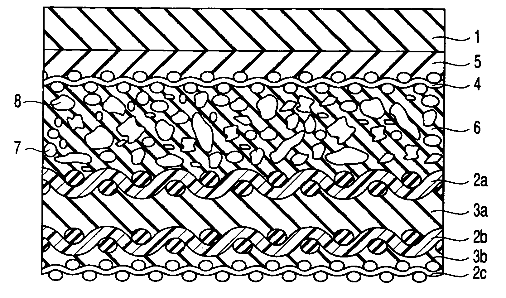
[0106] Prepared as the fabric layers were three cotton cloths each having a thickness of about 0.4 mm. Then, one surface of the cotton cloth 2a forming the upper fabric cloth layer was coated with the rubber paste B in a thickness of 0.3 mm so as to obtain an unvulcanized compressibl...

example 2

[0111] Rubber paste C was obtained by adding 3 parts by weight of microballoons substantially equal to those referred to in Example 1 to the rubber paste A of the composition similar to that referred to in Example 1.

[0112] Prepared as the rubber paste for the compressible layer was the rubber paste B equal to that referred to in Example 1.

[0113] An unvulcanized compressible rubber blanket having a thickness of about 2.1 mm was prepared as in Example 1, except that used was the rubber paste C in the unvulcanized adhesive layer.

[0114] After the unvulcanized compressible rubber blanket was wound around a metal drum, the unvulcanized compressible rubber blanket was heated at 150° C. for 6 hours in a vulcanizing can so as to finish the vulcanization.

[0115] Further, the vulcanized compressible rubber blanket was cooled, followed by polishing the surface rubber layer with a sand paper of 240 mesh so as to obtain a compressible blanket constructed as shown in FIG. 1 and having a thickne...

example 6

[0132] Prepared as the rubber paste for the adhesive layer was rubber paste A equal in composition to the rubber paste A referred to in Example 1. Also prepared as the rubber paste for the compressible layer was rubber paste B equal in composition to rubber paste B referred to in Example 1.

[0133] Prepared as the fabric layers were three cotton cloths each having a thickness of about 0.4 mm. One surface of the cotton cloth 2a constituting the upper fabric layer was coated with the rubber paste B in a thickness of 0.3 mm, followed by pasting a cotton cloth 4 used as a reinforcing layer and having a thickness of about 0.4 mm to the coated rubber paste B (unvulcanized compressible layer).

[0134] After the unvulcanized compressible layer thus obtained was wound around a metal drum, heating was applied to the unvulcanized compressible layer at 150° C. for 6 hours within a vulcanizing can so as to finish the vulcanization.

[0135] After an unvulcanized adhesive layer 3a was formed by coati...


PUM

PropertyMeasurementUnit
Thicknessaaaaaaaaaa
Thicknessaaaaaaaaaa
Thicknessaaaaaaaaaa

Abstract

Disclosed is a compressible printing blanket in which voids are formed in the compressible layer by using microballoons, comprising at least two fabric layers, an adhesive layer interposed between adjacent fabric layers, a surface rubber layer, and a compressible layer arranged between the at least two fabric layers and the surface rubber layer and containing spherical voids and voids having a shape other than a sphere in a ratio defined in formula given below: S1:S2=20:80 to 95:5   (1) where, S1 denotes the number of spherical voids per unit area in a cross section of the compressible layer, and S2 denotes the number of voids having a shape other than a sphere per unit area in a cross section of the compressible layer.

Description

CROSS-REFERENCE TO RELATED APPLICATIONS [0001] This is a Continuation-in-Part Application of PCT Application No. PCT / JP01 / 08456, filed Sep. 27, 2001, which was not published under PCT Article 21(2) in English. BACKGROUND OF THE INVENTION [0002] 1. Field of the Invention [0003] The present invention relates to a compressible printing blanket and a method of manufacturing a compressible printing blanket. [0004] 2. Description of the Related Art [0005] A method of manufacturing a laminated printing blanket is disclosed in, for example, U.S. Pat. No. 4,770,928. It is disclosed in this prior art that an intermediate compressible layer is prepared by dispersing microcapsules consisting of a copolymer between, for example, acrylonitrile and vinylidene chloride in an elastomeric material, and that the intermediate compressible layer thus prepared is vulcanized for 1 to 12 hours at a temperature lower than the melting point of the microcapsule, e.g., at about 110° F. (43° C.) to 170° F. (77°...

Claims


Application Information

Patent Timeline
IPC IPC(8): B41G7/00B41L47/02B29C70/02B29C70/08B29C70/66B32B5/18B32B7/12B32B25/10
CPCB29C70/025Y10T428/24504B29C70/66B32B3/26B32B5/02B32B5/18B32B5/26B32B7/12B32B9/02B32B9/047B32B25/10B32B33/00B32B37/12B32B2264/025B32B2274/00B32B2305/18B32B2307/302B32B2307/558B32B2307/732B32B2307/75B32B2559/00B41F13/193B41N10/04Y10S428/909B41N2210/04B41N2210/14Y10T428/2984Y10T428/2927Y10T428/24496Y10T428/28B29C70/086Y10T442/3325Y10T428/249975Y10T428/31504Y10T442/3366Y10T428/31569Y10T428/249982Y10T442/335Y10T442/3642Y10T428/249978Y10T428/249953Y10T428/24998Y10T442/3431
Inventor OGAWA, YOSHIHARUFURUTA, HISASHIINOUE, AKIYOSHI
Owner KINOYOSHA CO LTD
Why Eureka
Try Eureka