Organic light emitting diode (oled) with contrast enhancement features

a technology of organic light and diodes, applied in the direction of discharge tubes/lamp details, discharge tubes luminescnet screens, electric discharge lamps, etc., can solve the problems of reducing the backward emitted light towards the rear of the display, partially negating the advantages of constructive interference, and not being suitable for prior art structures

Inactive Publication Date: 2006-11-30
LUXELL TECH
View PDF7 Cites 21 Cited by
  • Summary
  • Abstract
  • Description
  • Claims
  • Application Information

AI Technical Summary

Benefits of technology

[0009] It is therefore an object of the present invention to provide a display with contrast enhancement feature that mitigates or obviates at least one of the above-identified disadvantages of the prior art.

Problems solved by technology

However, these prior art structures may not be suitable where it is desired to actually utilize the reflectivity of the rear cathode in order to boost the amount of light emitted from the device.
Put in other words, while the above-mentioned prior art devices reduce ambient light that reaches the rear cathode of the display, the prior art devices also tend to reduce the light that is backwardly emitted towards the rear of the display.
Indeed, in certain prior art OLED displays it is known to select an appropriate emitting region portion of the light emitting layer, to cooperate with the reflective electrode, in order to achieve a total phase shift of rearwardly emitted light of about 360°, such that the two light waves constructively interfere, thereby enhancing the brightness of the device.
However, as with the other prior art systems discussed above, back reflection of the light generated within the light emitting layers gives rise to destructive interference, which partially negates the advantages of the constructive interference.

Method used


Image

  • Organic light emitting diode (oled) with contrast enhancement features
  • Organic light emitting diode (oled) with contrast enhancement features
  • Organic light emitting diode (oled) with contrast enhancement features

Examples


Embodiment Construction

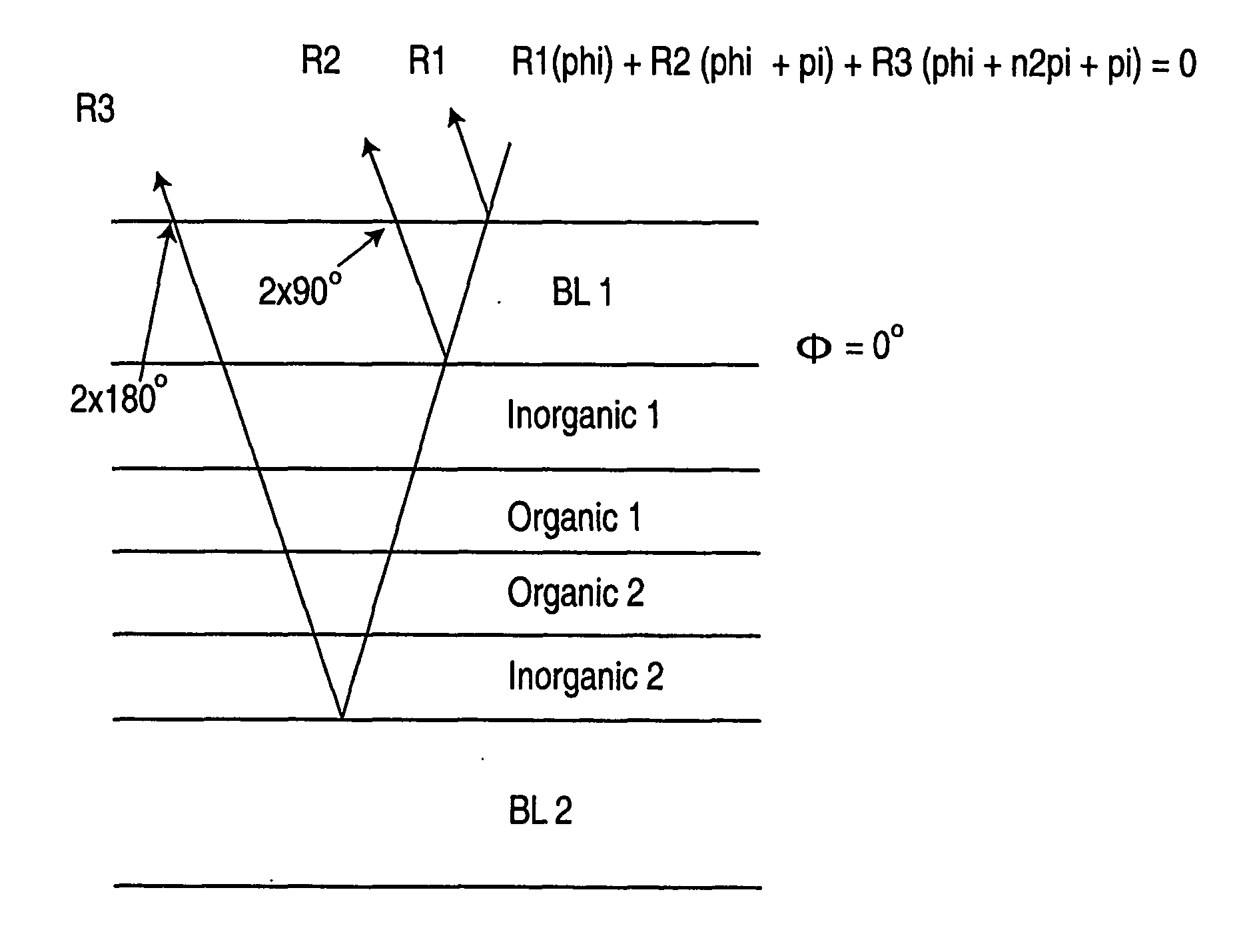
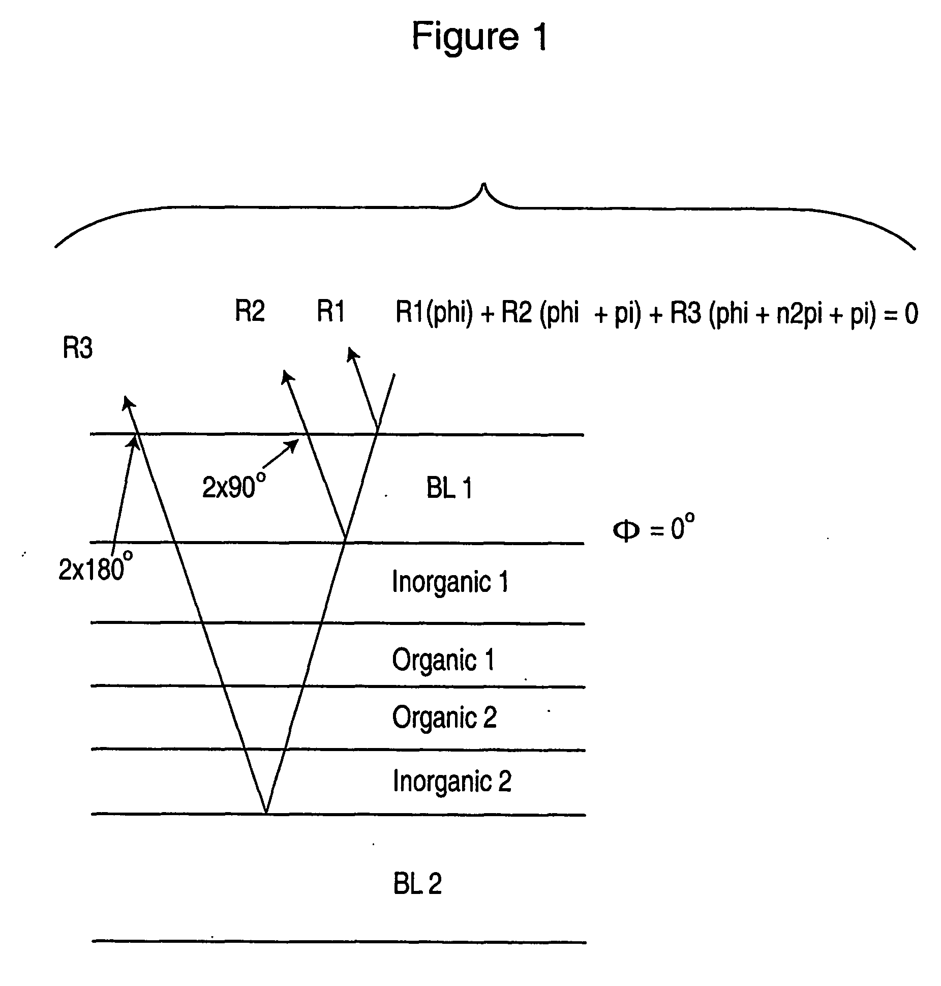
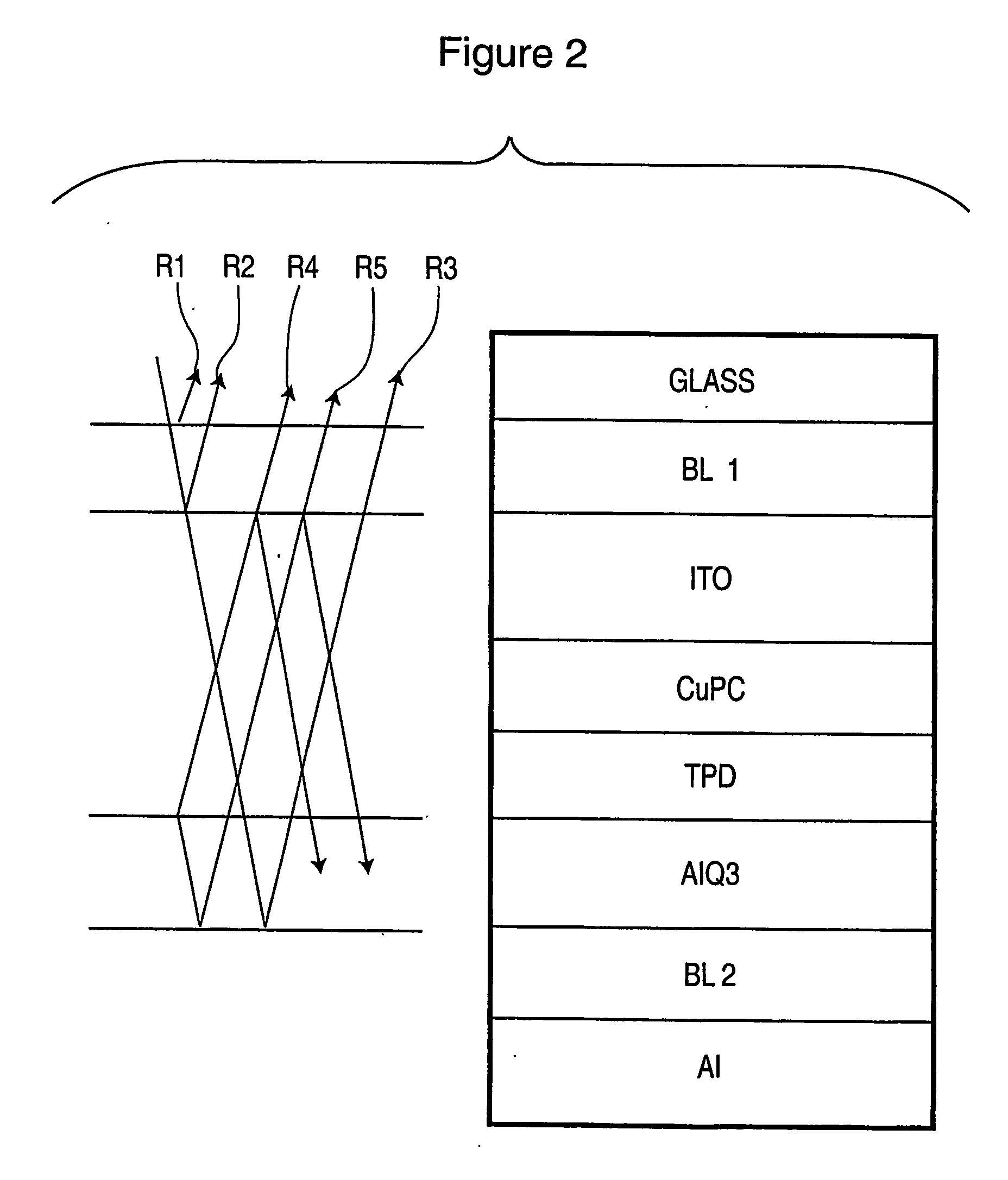
[0016] Referring now to FIG. 1, a semi-reflecting thin film BL 1 is disposed adjacent one side of a microcavity comprising inorganic layers such as ITO, AlSiO, etc. (identified in FIG. 1 as Inorganic 1, Inorganic 2) between which are disposed light emitting layers (identified as Organic 1, Organic 2), while a reflective structure BL 2 is disposed adjacent the opposite side of the microcavity. As discussed below in connection with FIGS. 2 and 3, the layer BL 2 may either be fully reflecting, or may instead partially transmit and phase shift light that is reflected off of a further fully reflective layer (e.g. Al layer). The light emitting layers generate light through electroluminescence and are fabricated from material that is nominally transparent to ambient light entering the device, and which causes a phase shift of that ambient light, as will be discussed in greater detail below.

[0017] Semi-reflecting structure BL 1 may comprise a single-layer film or a multi-layer film, as dis...


PUM


Abstract

An organic electroluminescent device is provided having emitting layers with materials and thicknesses that provide constructive optical interference of emitted light. The device includes additional layers that provide contrast enhancement through destructive optical interference of ambient light entering the device.

Description

FIELD OF THE INVENTION [0001] The present invention relates to electroluminescent devices, and more particularly relates to contrast enhancement filters that are applied to electroluminescent devices. BACKGROUND OF THE INVENTION [0002] Known contrast enhancement filters include optical interference filters as described in U.S. Pat. No. 5,049,780 to Dobrowoiski and U.S. Pat. No. 6,411,019 to Hofstra, the contents of which are incorporated herein by reference. In certain teachings of Dobrowolski and Hofstra contrast enhancement is provided by an optical interference member that is placed in front of a reflective rear electrode or reflective rear cathode. As more particularly described therein, reflections of ambient light off of the rear electrode or rear cathode are used in conjunction with the optical interference member to create at least two, out-of-phase, wave forms of ambient light, which interfere with each other to cause at least some cancellation of each other and thereby red...

Claims


Application Information

Patent Timeline
Patent Type & Authority Applications(United States)
IPC IPC(8): H05B33/00H01L51/52
CPCH01L51/5281H01L51/5265H10K50/852H10K50/86H05B33/24
Inventor WOOD, RICHARDPJOHNSON, DAVID J.
Owner LUXELL TECH
Why Eureka
Try Eureka