Eureka AIR delivers breakthrough ideas for toughest innovation challenges, trusted by R&D personnel around the world.

Leveling device

Inactive Publication Date: 2006-11-30
DAUGHERTY CHARLES LEROY
View PDF7 Cites 15 Cited by
  • Summary
  • Abstract
  • Description
  • Claims
  • Application Information

AI Technical Summary

Benefits of technology

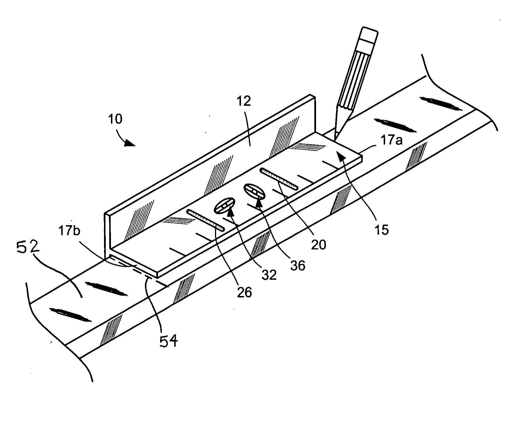
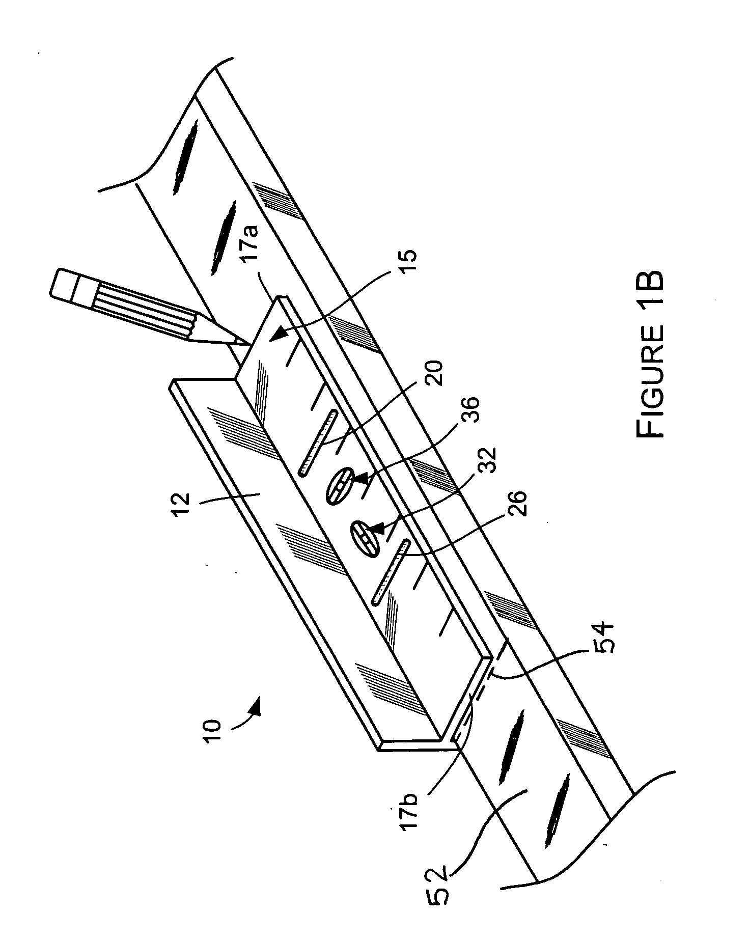
[0010] According to one aspect, the present invention provides a measuring device for rapidly performing repetitive measurements includes a base for supporting the measuring device upright upon a generally horizontal surface and minimizing the tendency of the measuring device to overturn. A generally-rigid template spans a primary distance between first and second terminal ends of the template, said primary distance being suitable to space a building structure apart from an adjacent building structure to establish a desired on-center spacing between those building structures. A marker is also provided to the template and separated a secondary distance from a first terminal end of the template. The secondary distance is the distance a secondary building structure is to be spaced from an adjacent secondary building structure to establish a desired on-center spacing between those secondary building structures.
[0011] According to another aspect, the present invention provides a measuring device for rapidly performing repetitive measurements commonly encountered while building a structure. The measuring device includes a base for supporting the measuring device upon a generally horizontal surface and minimizing the tendency of the measuring device to overturn. A generally-rigid template is coupled to the base and has terminal ends separated by a distance of about 15 15 / 16 inches, and a marker separated from at least one of the terminal ends of the template a distance of 5 5 / 16 inches to indicate a measurement of that distance.

Problems solved by technology

However, the tape measure is flexible and must be uncoiled from within its housing each time a measurement is desired, making it cumbersome for performing repetitive measurements.
Further, the tape measure provides no indication whether the base plate on which it rests is level, or whether a stud is plumb.
The framer is typically required to observe the stud and measuring scale from a side, which is often inconvenient when the measurements are made close to the floor.
Although such a block of wood can accurately reproduce the same spacing between adjacent studs along the length of the wall, it is useless for establishing a predetermined spacing between members that are to be spaced a distance other than 16 inches on center.
Further, the block of wood provides no measurement scale and no indication of whether a surface deviates from either a horizontal or vertical orientation.

Method used


Image

  • Leveling device
  • Leveling device
  • Leveling device

Examples


Embodiment Construction

[0019] Certain terminology is used herein for convenience only and is not to be taken as a limitation on the present invention. Relative language used herein is best understood with reference to the drawings, in which like numerals are used to identify like or similar items. Further, in the drawings, certain features may be shown in somewhat schematic form.

[0020]FIG. 2 is a schematic illustration of a measuring device for rapidly performing repetitive measurements, such as spacing adjacent framing studs apart 16 inches on center. An example of a framing stud is a piece of lumber sold as a 2 inch×4 inch piece of lumber having any desired length, wherein said piece of lumber is referred to herein as a “stud” and a “2×4.” Although sold as lumber having the dimensions of 2 inches (thickness) by 4 inches (width), 2×4s are not actually 2 inches by 4 inches. When each 2×4 is first rough sawn from the log, its dimensions are a true 2 inches by 4 inches. But the drying process and subsequen...


PUM


Abstract

A measuring device for rapidly performing repetitive measurements includes a base for supporting the measuring device upright upon a generally horizontal surface and minimizing the tendency of the measuring device to overturn. A generally-rigid template spans a primary distance between first and second terminal ends of the template, said primary distance being suitable to space a building structure apart from an adjacent building structure to establish a desired on-center spacing between those building structures. A marker is also provided to the template and separated a secondary distance from a first terminal end of the template. The secondary distance is the distance a secondary building structure is to be spaced from an adjacent secondary building structure to establish a desired on-center spacing between those secondary building structures.

Description

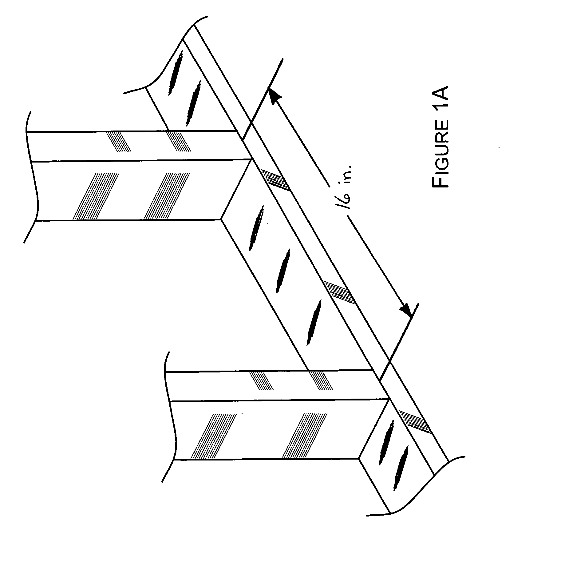
CROSS-REFERENCE TO RELATED APPLICATIONS [0001] This application claims the benefit of U.S. Provisional Application No. 60 / 683,730, filed on May 24, 2005.BACKGROUND OF THE INVENTION [0002] 1. Field of the Invention [0003] The present invention is directed generally to a measuring device, and more specifically, to a measuring device for repeatedly performing the same or similar measurements of a predetermined distance. [0004] 2. Description of Related Art [0005] Traditionally, when framing a wall or other structure being built, support members commonly referred to as “studs” must be spaced from each other such that their centers are located 16 inches apart, as shown in FIG. 1A. The studs can be load bearing, and provide support for the drywall or other wall covering, which gives the wall a finished appearance. To layout the location of the studs, a measuring device such as a tape measure is commonly used to measure from the center of a stud at one end of the wall along a base plate th...

Claims


Application Information

Patent Timeline
IPC IPC(8): G01D21/00
CPCB43L7/00B43L12/00G01C9/26G01B3/04E04F21/003
Inventor DAUGHERTY, CHARLES LEROY
Owner DAUGHERTY CHARLES LEROY
Why Eureka
Eureka Blog
Learn More