
Portable gas sensor and method for calibrating the same

a gas sensor and portability technology, applied in the field of gas sensors, can solve the problems of increased deviation in measurement of gas sensors, increased risk of gas explosion and gas poisoning, and different types of gas sensors, and achieve the effect of convenient calibration by users

Inactive Publication Date: 2006-11-23
SEJU ENG CO LTD
View PDF6 Cites 39 Cited by
  • Summary
  • Abstract
  • Description
  • Claims
  • Application Information

AI Technical Summary

Benefits of technology

[0013] It is, therefore, an object of the present invention to provide a portable gas sensor allowing a convenient calibration by a user and a method for calibrating the same.

Problems solved by technology

As industrial developments have been accelerated ever since the Industrial Revolution, problems related to atmospheric pollution caused by using such hazardous gases as carbon monoxide (CO), hydrogen sulfide (H2S), sulfur dioxide (SO2) and nitrogen oxide (NOx) have been increasingly issued.
Also, danger of gas explosion and gas poisoning has been alerted.
For a conventional portable gas sensor, there exists a problem of frequent errors caused by a different operating mechanism from a gas alarm which is continuously operated for 24 hours a day and 365 days a year.
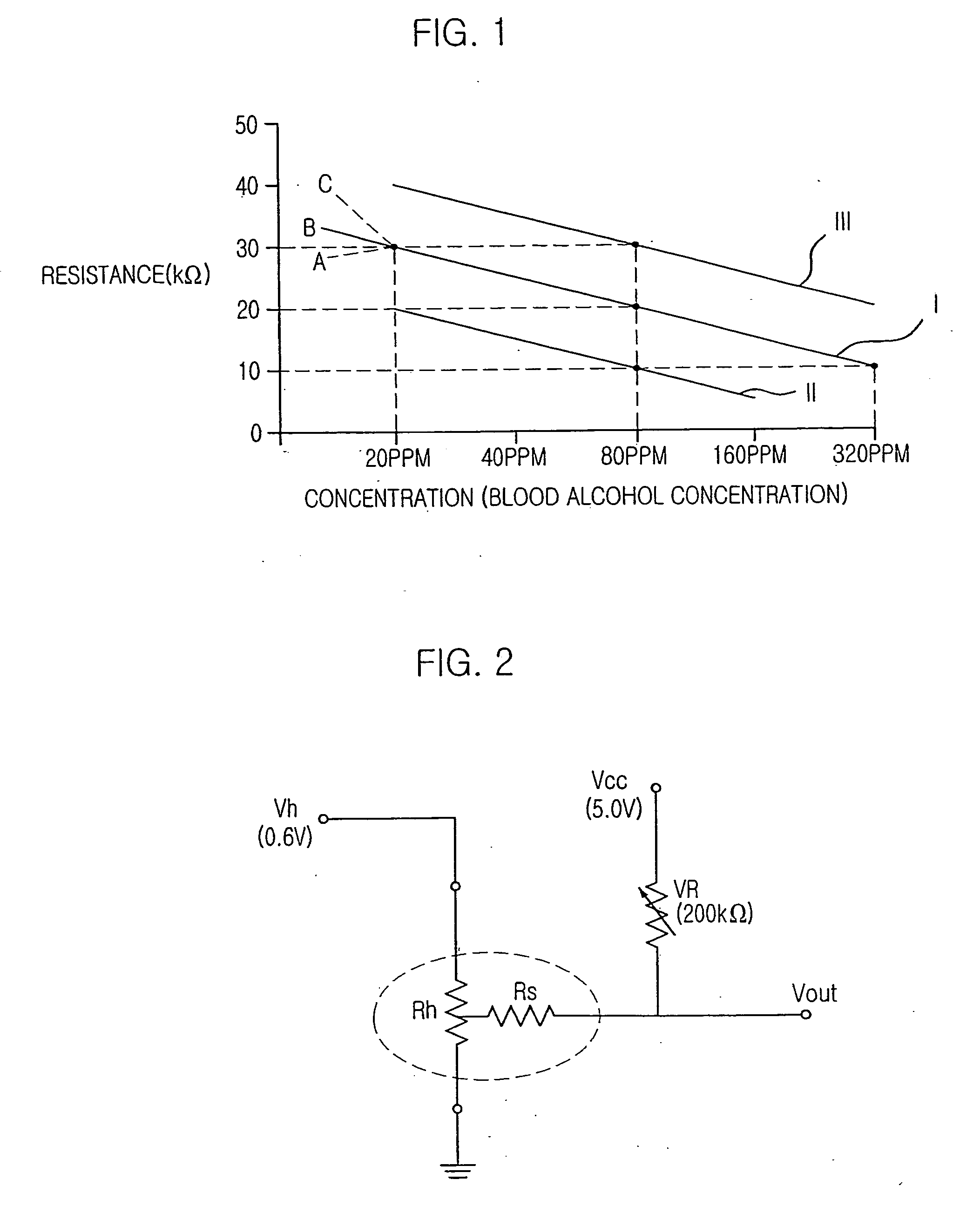
However, this type of the gas sensor also reacts with undesired gases depending on external environmental factors, e.g., temperature, humidity, atmospheric pressure and subsequently changes a reference value of the gas sensor.
As a result, measurements by the gas sensor become deviated in a greater extent.
That is, there exists a high risk of deviations in the detection result according to changes in characteristics of the gas sensor.
However, it is difficult to obtain a conveniently applicable reference gas, and the calibration proceeds manually by a manufacturer since the calibration skill has not been developed yet.

Method used


Image

  • Portable gas sensor and method for calibrating the same
  • Portable gas sensor and method for calibrating the same
  • Portable gas sensor and method for calibrating the same

Examples


Embodiment Construction

[0023] Hereinafter, a preferred embodiment of a portable gas sensor allowing a convenient calibration by a user and a method for calibrating the same will be described in detail referring to the accompanying drawings.

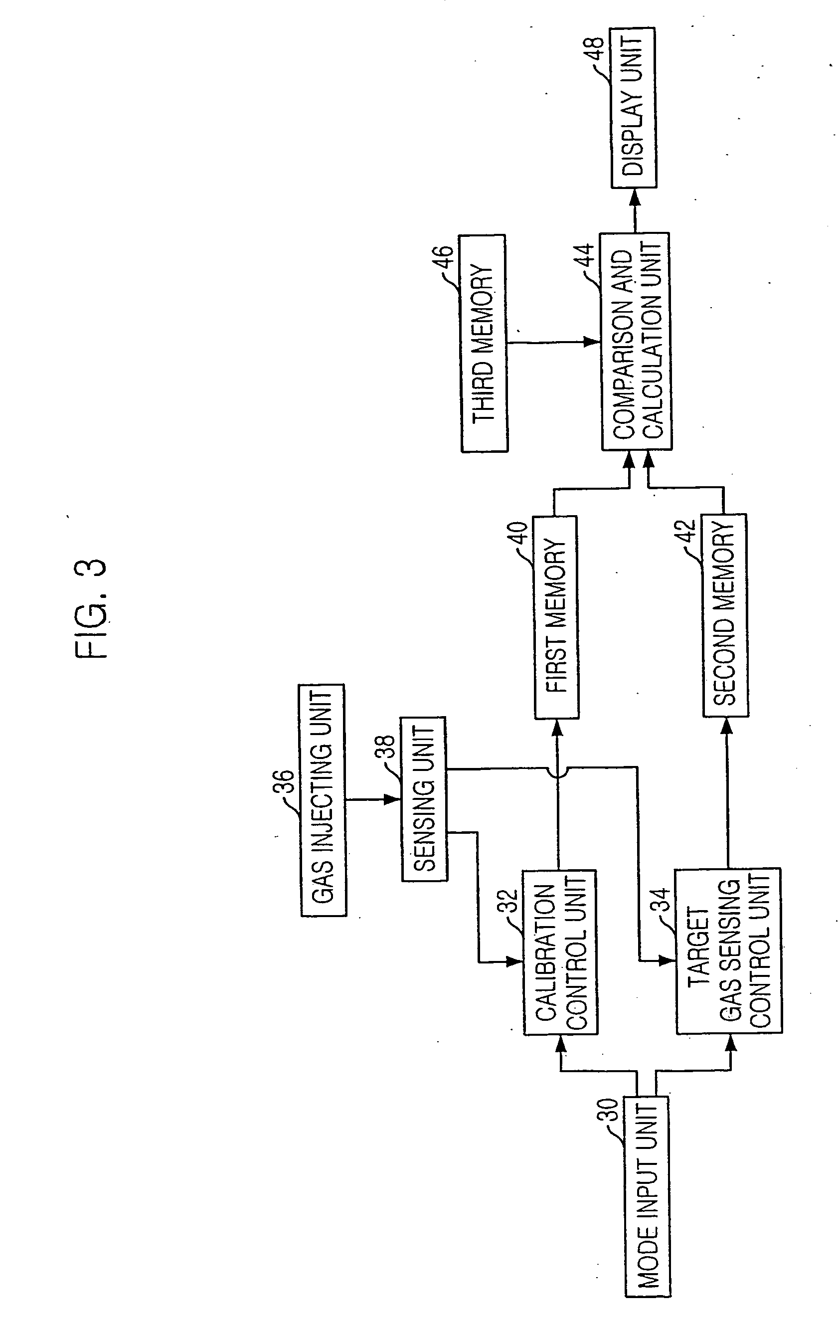
[0024]FIG. 3 is a block diagram showing the portable gas sensor in accordance with the preferred embodiment of the present invention.

[0025] Referring to FIG. 3, the portable gas sensor includes a mode input unit 30, a calibration control unit 32, a target gas sensing control unit 34, a gas injecting unit 36, a sensing unit 38, a first memory 40, a second memory 42, a comparison and calculation unit 44, a third memory 46 and a display unit 48. A user selects a calibration operation mode or a target gas measuring operation mode of the portable gas sensor through the mode input unit 30. A gas from an external source is injected into the gas injecting unit 36, and the injected gas reacts with a sensing material of the sensing unit 38. Because of the chemical reaction betw...


PUM


Abstract

The present invention provides a portable gas sensor having a sensing material reacted with a target gas. The portable gas sensor includes a mode input unit for selecting an operation mode; a gas inhaling unit for accepting an external gas; a sensing unit for outputting a voltage value corresponding a varied resistance value of the sensing material reacted with the external gas; a first memory for storing a reference voltage value corresponding a resistance value of the sensing material reacted with a reference gas; a calibration control unit for storing a first voltage value corresponding to a resistance value of the sensing material reacted with a substitute reference gas in the first memory by substituting the reference voltage value; a target gas sensing control unit for storing a second voltage correspond to a resistance value of the sensing material reacted with the target gas into the second memory; a comparison and calculation unit for comparing and calculating the first voltage value and the second voltage value; and a display unit for displaying a concentration of the target gas calculated in the comparison and calculation unit.

Description

TECHNICAL FIELD [0001] The present invention relates to a gas sensor; and, more particularly, to a portable gas sensor and a method for calibrating the same. BACKGROUND ART [0002] As industrial developments have been accelerated ever since the Industrial Revolution, problems related to atmospheric pollution caused by using such hazardous gases as carbon monoxide (CO), hydrogen sulfide (H2S), sulfur dioxide (SO2) and nitrogen oxide (NOx) have been increasingly issued. Also, danger of gas explosion and gas poisoning has been alerted. [0003] After the first report on a catalytic combustion-type sensor by Johnson, various types of the gas sensor have been developed. Particularly, a semiconductor-type gas sensor, first discovered by Seiyama and Taguch, detects the presence or absence of a specific gas and its concentration through estimation of changes in resistance by using sintered materials, e.g., tin dioxide (SnO2), zinc oxide (ZnO), and indium trioxide (In2O3), which are metal-oxide...

Claims


Application Information

Patent Timeline
IPC IPC(8): G01N33/00G01N33/497G01N27/407
CPCG01N33/0006G01N33/4972G01N33/497G01N27/407
Inventor LEE, WON BAE
Owner SEJU ENG CO LTD
Learn More