
Master-slave manipulator system and this operation input devcies

a manipulator and master-slave technology, applied in the direction of electric programme control, program control, instruments, etc., can solve the problems of complex control and vibrating behavior, increase in the size of the operation input device, and excessive force applied to the operator, and achieve good operability and high reliability

Active Publication Date: 2006-11-23
HITACHI LTD
View PDF8 Cites 104 Cited by
  • Summary
  • Abstract
  • Description
  • Claims
  • Application Information

AI Technical Summary

Benefits of technology

The present invention provides a master-slave manipulator system and an operation input device that can present obstacles or limits to the range of motion of the manipulator without using a motor in the input device. The operation input device has a mode change-over mechanism with three modes that selectively transmit power in one direction or reverse. The system can detect and acquire geometrical or obstacle data in the operation range of the manipulator and use it to set areas where the manipulator can operate. The mode change-over mechanism can be a two-way clutch, a solenoid, or a rotating joint mechanism. The operation input device can also have a grip opening and closing mechanism and a diagnostic tool for acquiring geometrical data. The controller can select the mode change-over mechanism to limit the operation range of the manipulator and provide force feed-back when the manipulator comes into contact with an object. The system and device have high reliability, small size, and good operability.

Problems solved by technology

However, in a usual master-slave manipulator system, even if an obstacle, a hazard area or the like to be avoided is present in an operation range of a manipulator arm, when the operation input device is moved to a position corresponding to the obstacle or the hazard area, the manipulator arm would hit the obstacle or enter the hazard area, which is caused a problem.
However, the actuator provided in the operation input device would cause an increase in the size of the operation input device, and additionally, a failure thereof or the like results in an excessive large force applied to the operator.
Should the operation range and a wall be exhibited as a force feed-back with the use of the actuator in the operation input device, the manipulator system causes problems of complicated control and vibrating behavior at an interface between a zone where a wall is sensed and a free operation zone.
Further, in a circumstance where noise causes a problem, a usual motor could be hardly used as the actuator.
For example, a surgical support manipulator system utilizing an MRI unit as a diagnostic tool can hardly use an operation input device utilizing a motor which would cause noise interference with the MRI unit.
It is noted that, in the configuration disclosed in the patent document 1, there is not required a motor because of restricting the operation range of the operation input device by physically arranging the position restricting member and pins, but it is difficult to control the operation, in a case that the position of an obstacle or a possible operation range varies momentarily.
The patent document 3 discloses the proposal of presenting a force feed-back in the operation input device when the slave arm makes contact with an object, but it is not adapted to be use for avoiding an obstacle or a hazard zone.

Method used


Image

  • Master-slave manipulator system and this operation input devcies
  • Master-slave manipulator system and this operation input devcies
  • Master-slave manipulator system and this operation input devcies

Examples


Embodiment Construction

[0034] Explanation will be hereinbelow made of an embodiment according to the present invention with reference to FIGS. 1 to 7.

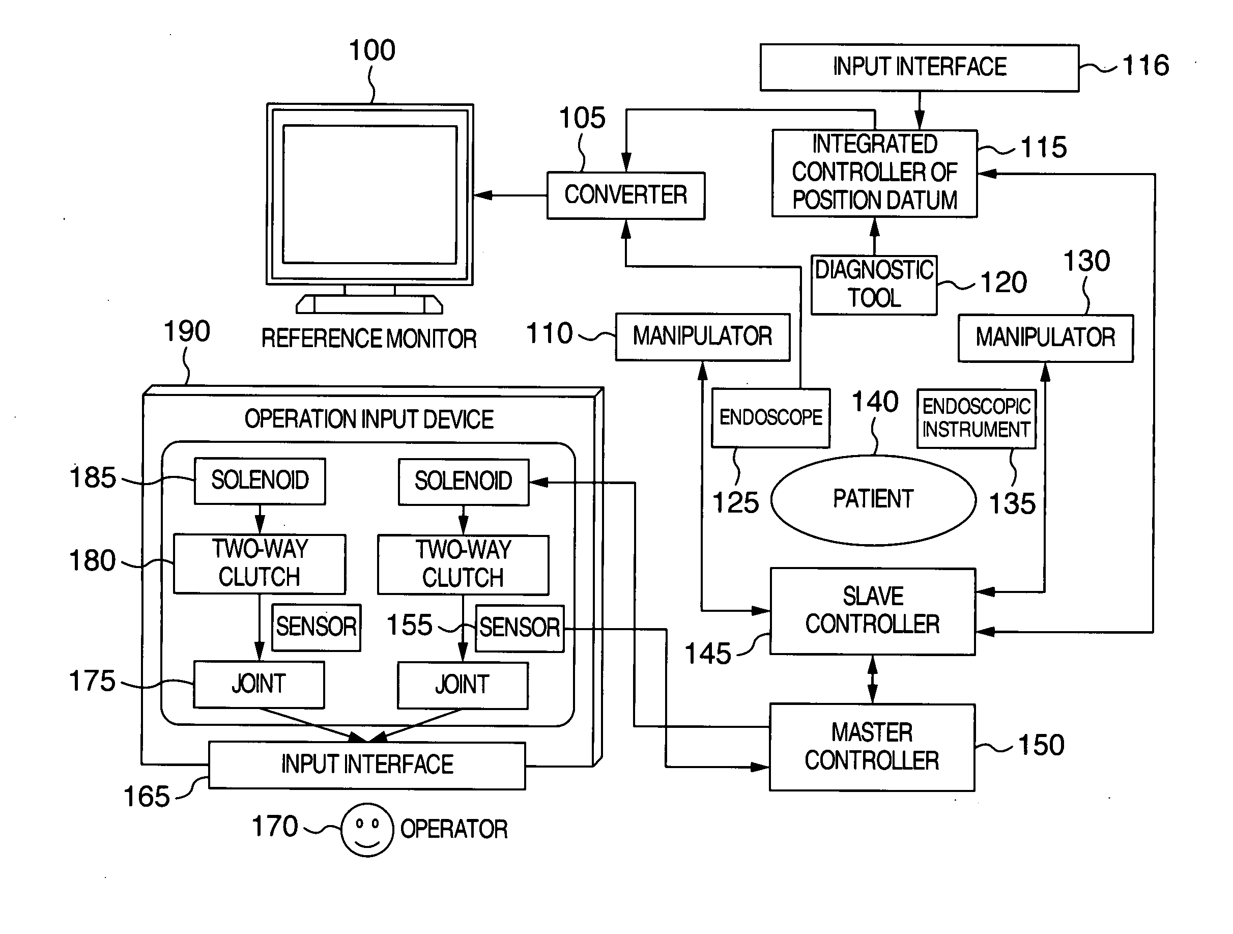
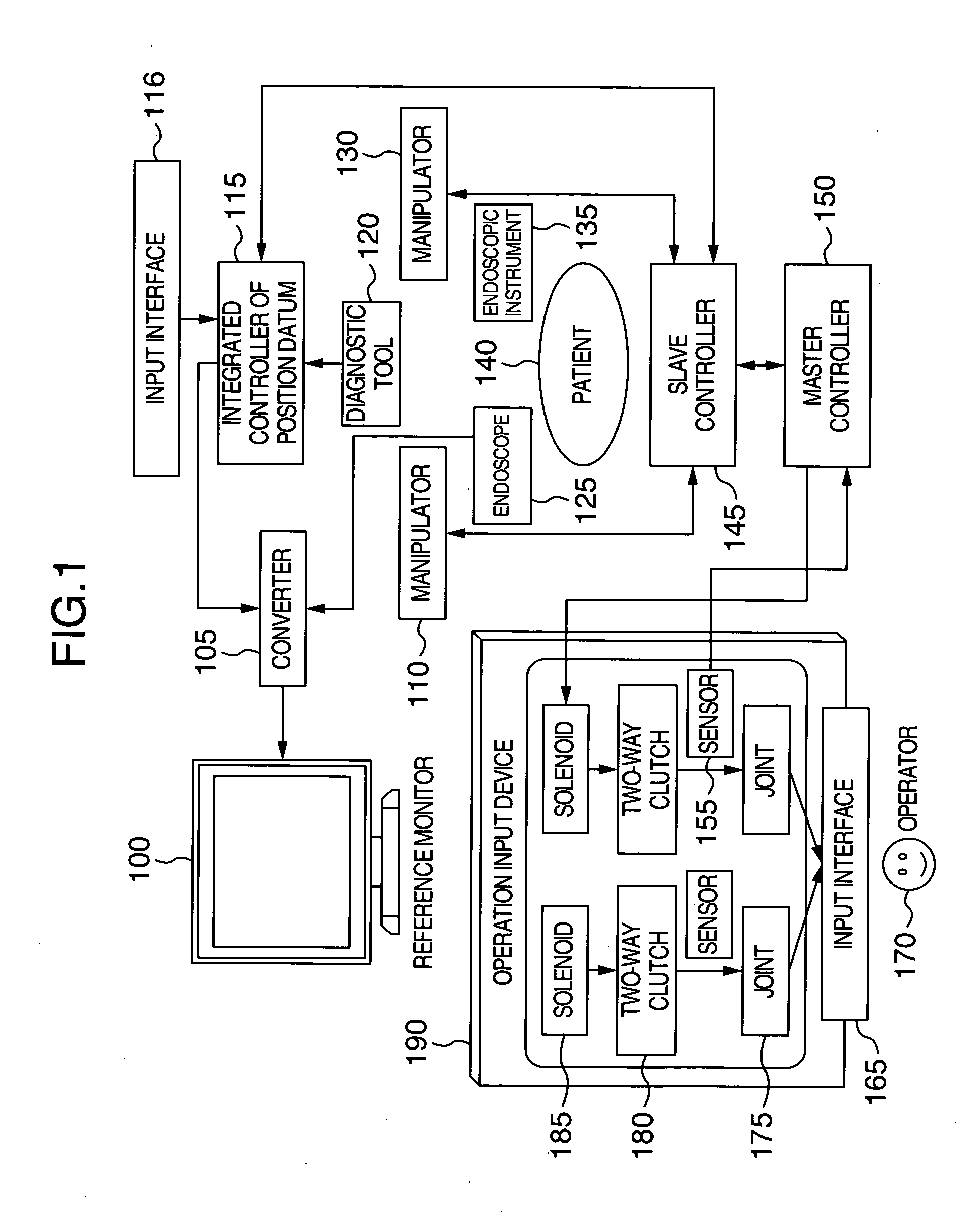
[0035]FIG. 1 shows an overall configuration of a master-slave manipulator system according to an embodiment of the present invention, which is used as a surgical support system as an example.

[0036] An operator 170 may manipulate an endoscopic instrument 135 which is located at the distal end of a second manipulator 130 with the use of an input interface 165 of an operation input device 190, while referring to the endoscopic instrument 135 an image of which is picked up by an endoscope 125 held by a first manipulator 110. An image displayed on a reference monitor 100 is picked up from an affected part of the patient 140 by the endoscope 125 held by the first manipulator 110, and accordingly, the endoscopic instrument 135 may also fall in the viewing field of the endoscope 125 together with the affected part of the patient 140. It is noted that the first man...


PUM


Abstract

In a master-slave manipulator system capable of presenting an obstacle and a limit to an operating range as a force feed-back with no use of a motor in an operation input device and having high reliability, a small size and good operability, the system comprises a manipulator having an arm, an operation input device for moving the arm of the manipulator, and a controller for controlling the manipulator and the operation input device, and the operation input device is provided on joints with a mode change-over mechanism having three modes: of which, in a first mode, power is not transmitted; in a second mode, power is transmitted in one direction and is not transmitted in a reverse direction thereof; and in a third mode, power is transmitted in the reverse direction and is not transmitted in the one direction, selecting one of the above modes and changing over from one mode to the selected mode.

Description

BACKGROUND OF THE INVENTION [0001] The present invention relates to a master-slave manipulator system and this operation input devices. DESCRIPTION OF RELATED ART [0002] There have been developed many master-slave manipulator systems in which a manipulator is operated by an operation input device manipulated by the operator. [0003] However, in a usual master-slave manipulator system, even if an obstacle, a hazard area or the like to be avoided is present in an operation range of a manipulator arm, when the operation input device is moved to a position corresponding to the obstacle or the hazard area, the manipulator arm would hit the obstacle or enter the hazard area, which is caused a problem. [0004] In order to solve the above-mentioned problem, JP-A-7-124876 (patent document 1) discloses such a configuration that a position restricting member is arranged in an operation range of an operation input device, corresponding to a position of an obstacle against the manipulator arm, in ...

Claims


Application Information

Patent Timeline
Patent Type & Authority Applications(United States)
IPC IPC(8): G05B19/19B25J9/18A61B34/35A61B90/00
CPCA61B19/22G05B2219/45118A61B19/5212A61B2019/2223B25J3/04B25J9/1676B25J9/1689B25J13/02B25J19/0004G05B2219/39088G05B2219/39114G05B2219/40161G05B2219/40181G05B2219/40212G05B2219/40478A61B19/2203A61B34/70A61B90/361A61B34/30A61B34/37
Inventor KISHI, KOSUKEUMEKITA, KAZUHIRO
Owner HITACHI LTD
Learn More