Common rail for diesel engines

a diesel engine and common rail technology, applied in the direction of fuel injection apparatus, charge feed system, metal-working apparatus, etc., can solve the problems of applying auto-frettage, achieve excellent durability, increase the fatigue strength of inner pressure, and high compressive residual stress

Inactive Publication Date: 2006-11-23
USUI KOKUSAI SANGYO KAISHA LTD
View PDF2 Cites 3 Cited by
  • Summary
  • Abstract
  • Description
  • Claims
  • Application Information

AI Technical Summary

Benefits of technology

[0020] As described above, stress concentration at the peripheral edge of the branch hole is relaxed and autofrettage is then applied according to the invention. Thus, high compressive residual stresses can be made present in the whole common rail due to the synergistic effect of a decrease of stress concentration applied at the peripheral edge of the branch hole and autofrettage applied on the whole flow passage in the main pipe rail and the flow passage in the branch hole. Accordingly excellent durability can be expected also for the flow passage in the main pipe rail and the opening peripheral edge of the branch hole while fatigue strength for inner pressures is increased at the inner peripheral edge of the lower end of the branch hole.

Problems solved by technology

In common rails for diesel engines, however, disadvantages are caused when autofrettage is applied without application of further processings in the stock pipe as described herein.

Method used


Image

  • Common rail for diesel engines
  • Common rail for diesel engines
  • Common rail for diesel engines

Examples


Embodiment Construction

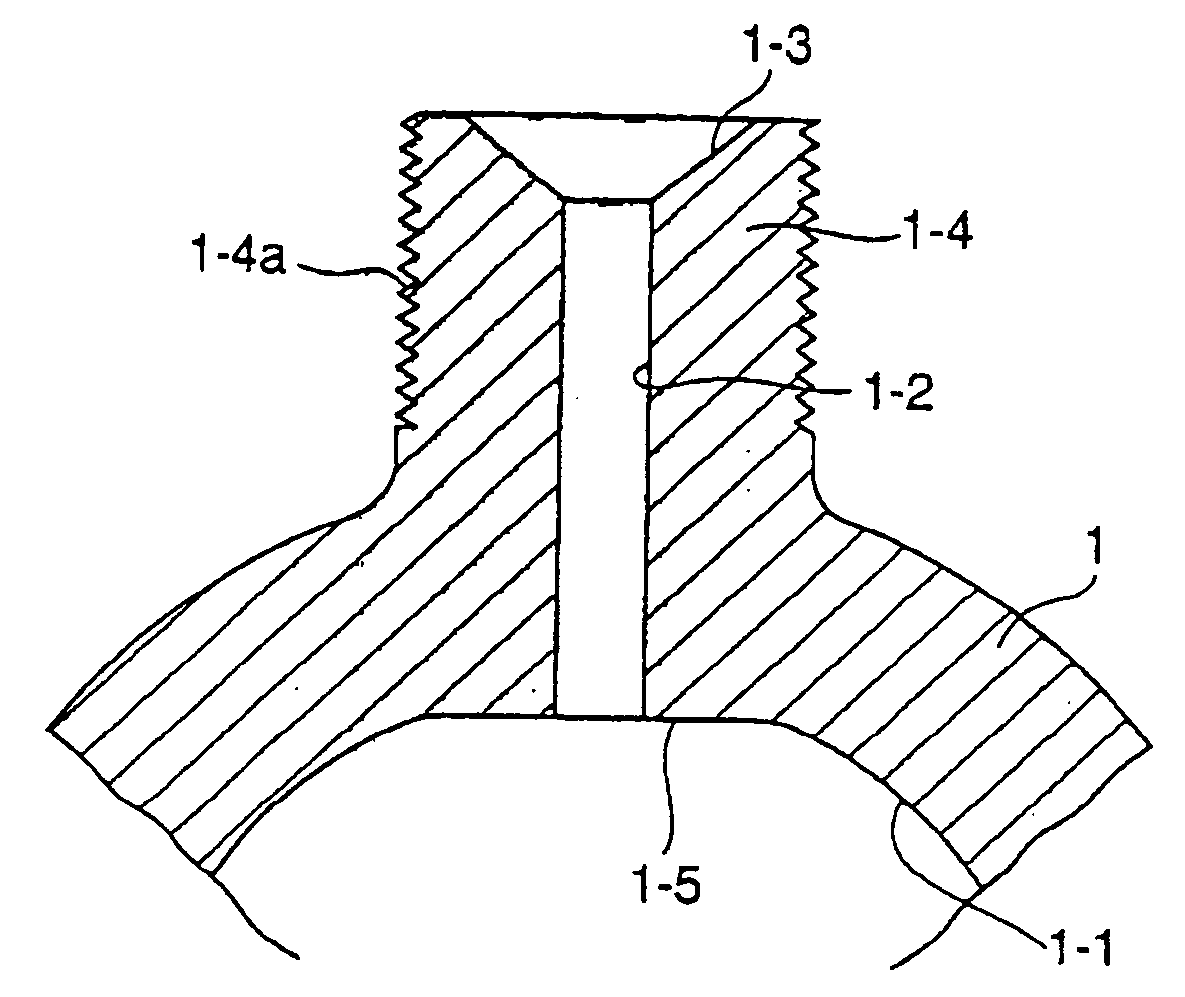
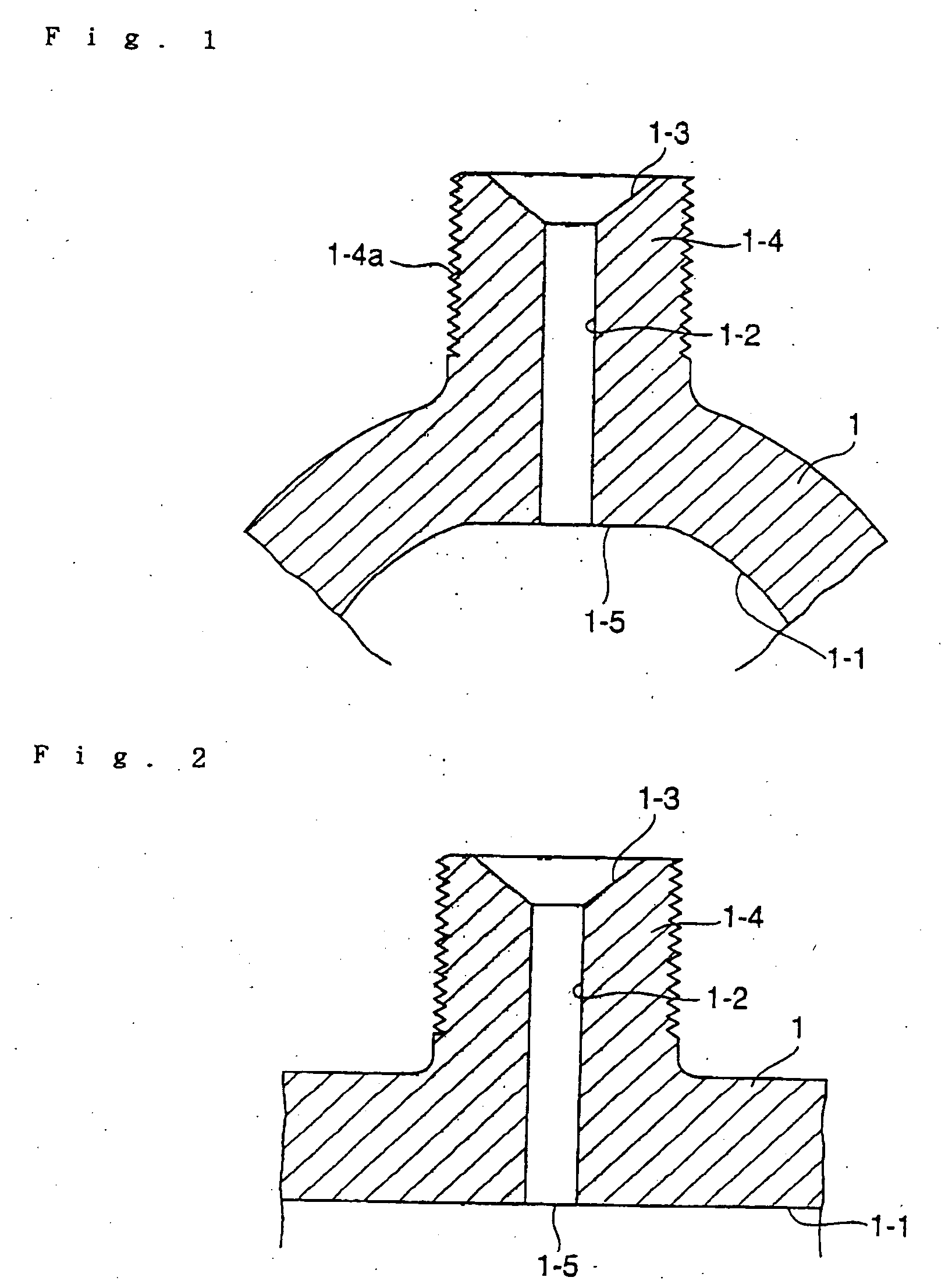
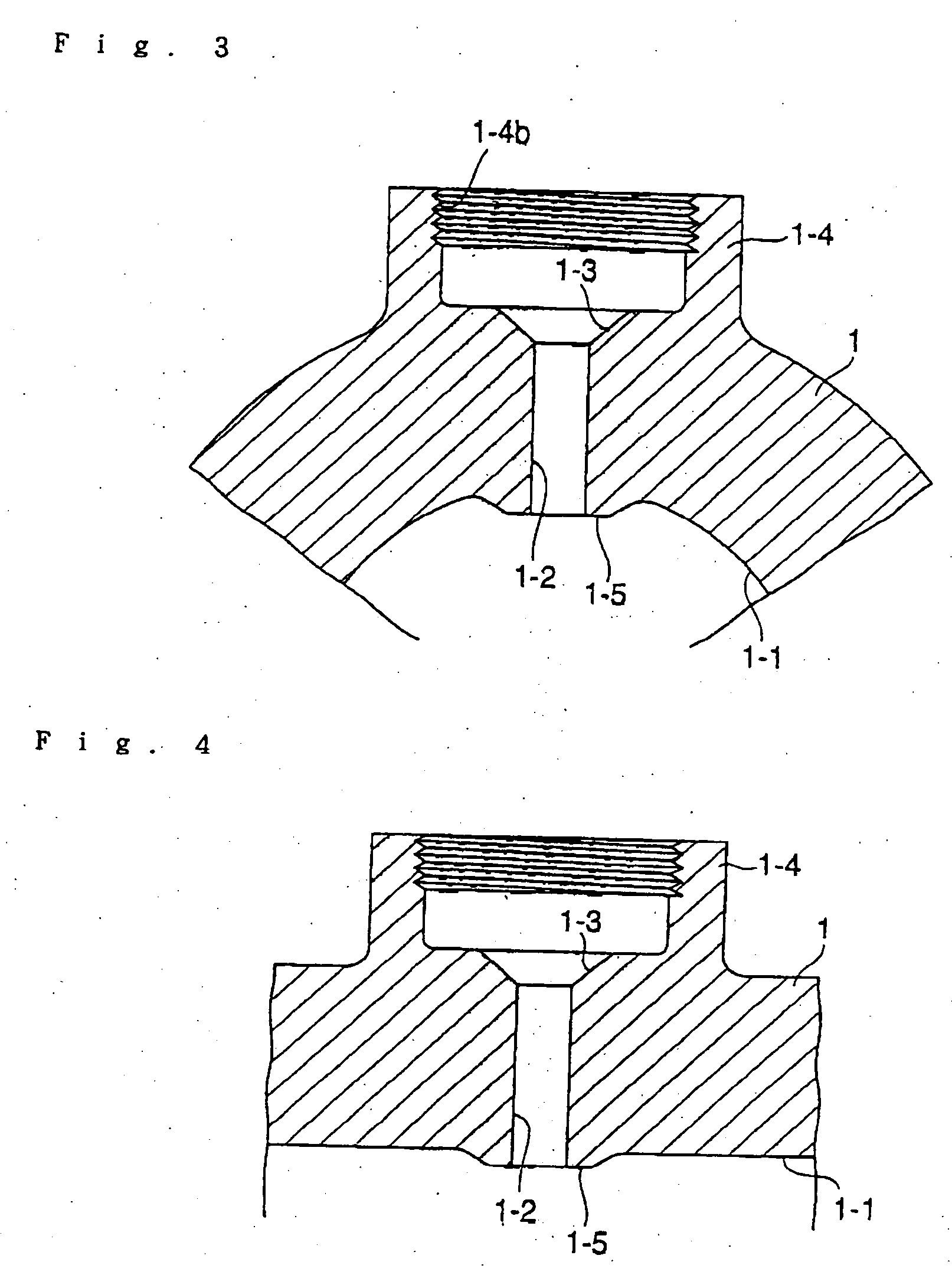
[0032] In the invention, reference numeral 1 denotes a main pipe rail, 1-1 a flow passage, 1-2 a branch hole, 1-3 a pressure-receiving seat surface, 1-4 a boss portion, 1-4a a male thread, 1-5 a flattened surface, 2 a branch pipe, 2-1 a flow passage, and 2-2 a projection.

[0033] The main pipe rail 1 or common rail shown in FIGS. 1 to 4 is a forging of a material S45C or the like. The main pipe rail 1 has a tubular portion, which is relatively thick-walled to have, for example, a diameter of 28 mm and a wall thickness 9 mm. An axial interior is subjected to machining, such as boring, gun drilling, or the like, to make the flow passage 1-1, and boss portions 1-4 are provided on a peripheral wall to be axially spaced from one another.

[0034] In the common rail shown in FIGS. 1 and 2, branch holes 1-2 having a predetermined diameter are formed in the boss portions 1-4 which are integral with the main pipe rail 1 The branch holes 1-2 communicate with the flow passage 1-1 of the main pipe...


PUM

PropertyMeasurementUnit
diameteraaaaaaaaaa
diameteraaaaaaaaaa
diameteraaaaaaaaaa

Abstract

A common rail for a diesel engine has a main pipe rail with an axial flow passage. Branch holes are made in the main pipe rail and communicate with the axial flow passage. The main pipe rail is worked to decrease stress concentration near the branch holes. The whole inner peripheral surface of the main pipe rail and the branch holes then is subjected to autofrettage processing to generate a compressive residual stress on the entire inner peripheral surface of the main pipe rail and the branch holes for increasing fatigue strength.

Description

[0001] This application is a divisional U.S. patent application Ser. No. 10 / 653,477, filed Sep. 2, 2003.BACKGROUND OF THE INVENTION [0002] 1. Field of the Invention [0003] The present invention relates to a common rail, such as high-pressure fuel manifolds, block rails, or the like, in a fuel injection system for diesel engines, and more particularly, to a common rail for diesel engines, in which portions of a branch hole or holes on a main pipe rail and a whole inner peripheral surface of the main pipe rail are enhanced in fatigue strength for inner pressures. [0004] 2. Description of the Related Art [0005] A common rail in a fuel injection system for diesel engines is shown in FIG. 7, and has a circular main pipe 11. The main pipe 11 has an internal flow passage 11-1. A branch hole 11-2 is provided in a peripheral wall of the main pipe 11 and communicates to the internal flow passage 11-1. The branch hole 11-2 leads to an outwardly opened pressure-receiving seat surface 11-3. A cy...

Claims


Application Information

Patent Timeline
Patent Type & Authority Applications(United States)
IPC IPC(8): B21D53/84F02M55/00F02M55/02
CPCF02M55/005Y10T29/49291F02M55/025F02M55/02
Inventor USUI, MASAYOSHI
Owner USUI KOKUSAI SANGYO KAISHA LTD
Why Eureka
Try Eureka