
Display device with a touch screen

a display device and touch screen technology, applied in the field of display devices with touch screens, can solve problems such as affecting the light detection accuracy of the sensor, and achieve the effects of reducing the influence of backlight or light, increasing touch detection accuracy, and suppressing power consumption

Active Publication Date: 2006-11-16
JAPAN DISPLAY INC +1
View PDF6 Cites 134 Cited by
  • Summary
  • Abstract
  • Description
  • Claims
  • Application Information

AI Technical Summary

Benefits of technology

[0006] It is therefore an object of the present invention is to provide a display device which, in a sensor output scan mode, can turn OFF backlight or can give black display of a panel to thereby reduce the influence of backlight or light from spontaneous light-emitting elements on a sensor part.
[0007] In the display device with a touch screen having optical sensors built therein for detecting a shade produced when external light coming into a liquid crystal display panel from its surface is shielded, a touch detection accuracy can be increased. Since the external light is utilized and no separate illumination light source is used, a power consumption can be suppressed in order to detect a touch.

Problems solved by technology

This affects the light detection accuracy of the sensor.

Method used


Image

  • Display device with a touch screen
  • Display device with a touch screen
  • Display device with a touch screen

Examples


embodiment 1

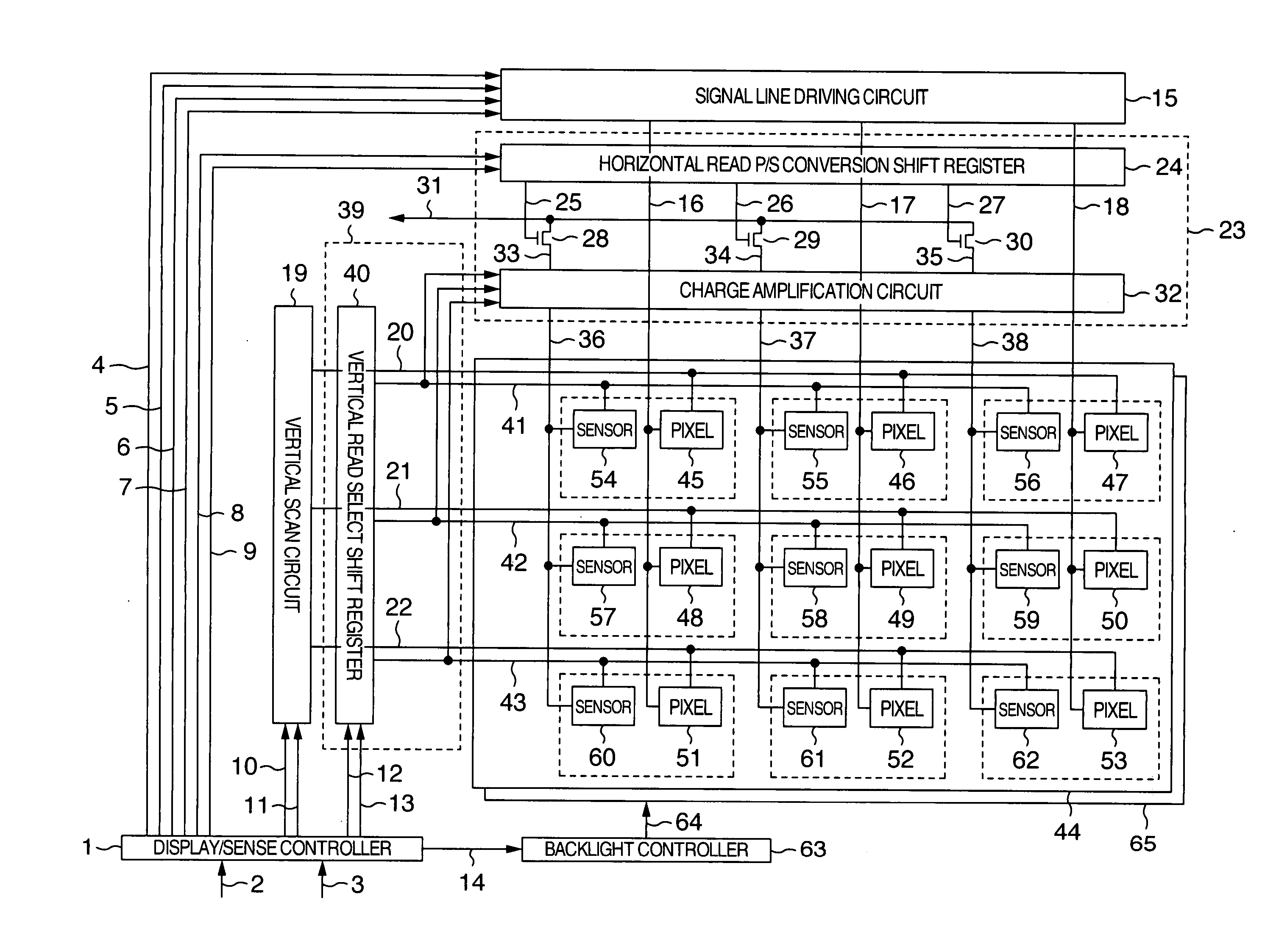
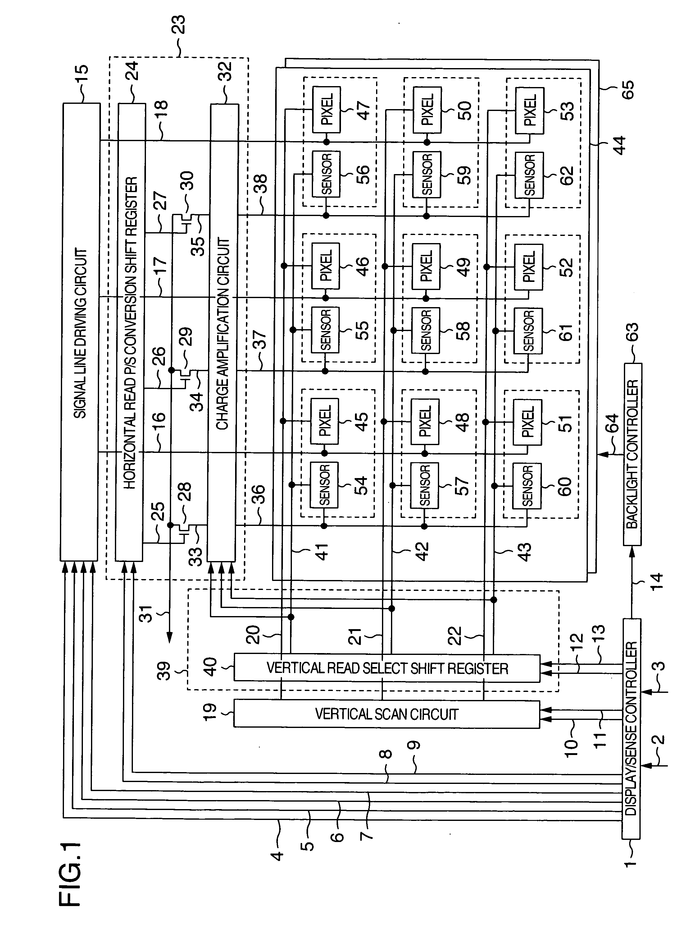
[0021]FIG. 1 schematically shows a display device with a touch screen in accordance with an embodiment of the present invention, wherein reference numeral 1 denotes a display / sense controller, numeral 2 denotes input display data, 3 denotes an input sync signal, 4 display data, 5 a horizontal start pulse, 6 a horizontal shift clock, 7 a horizontal latch clock, 8 a sense read start pulse, 9 a sense read shift clock, 10 a vertical start pulse, 11 a vertical shift clock, 12 a sense line select start pulse, 13 a sense line select shift clock, 14 a sense sync backlight control signal.

[0022] The display / sense controller 1, according to the input display data 2 and the input sync signal 3, generates the display data 4, the horizontal start pulse 5 indicative of start of one horizontal period, the horizontal shift clock 6 for shifting the horizontal start pulse sequentially in the horizontal direction, the horizontal latch clock 7 indicative of timing of collective output of display data c...

embodiment 2

[0085] Explanation will next be made as to black display control when a pixel is a spontaneous light-emitting element such as an organic EL.

[0086]FIG. 7 corresponds to FIG. 1, except that the display pixels 45 to 53 are replaced with spontaneous light-emitting display pixels 117 to 125, the backlight unit 65 is removed, the sense sync backlight control signal 14 is replaced with a sense sync black display control signal 126, the backlight controller 63 is replaced with a black display controller 127, and the backlight turn-ON control signal 64 is replaced with a black display control signal 128. With respect to the output scan of the display image sensor line, the embodiment 2 is substantially the same as the embodiment 1.

[0087] The display / sense controller 1 performs display substantially the same operation as in the prior art. That is, in the sense mode, the display / sense controller outputs the sense line select start pulse 12 and the sense line select shift clock 13, and also o...


PUM


Abstract

A display device with a touch screen having display pixels and optical sensors each arranged in a matrix. In the display device, a backlight controller controls a backlight unit to be turned ON in a data display duration and controls the backlight unit to be turned OFF in a sensor detection duration other than the data display duration. Consequently, the influence of backlight on a touch part when the shade of the touch part is to be detected, can be reduced and an accuracy in the detection of an optical sensor can be increased

Description

INCORPORATION BY REFERENCE [0001] The present application claims priority from Japanese application JP2005-139754 filed on May 12, 2005, the content of which is hereby incorporated by reference into this application. BACKGROUND OF THE INVENTION [0002] The present invention relates to a display device with a touch screen having sensors arranged in a matrix which illuminates a liquid crystal display panel by a backlight light source or displays an image by spontaneous light-emitting elements, and more particularly, to control of backlight to realize an increased detection accuracy in the sensors or control of the spontaneous light-emitting elements. [0003] Recent years have seen significant spread of a display panel which can be operated by touching the panel with use of a pen or operator's finger. As one of touch operation detecting systems, a system for building optical sensors into a liquid crystal display panel is enumerated. There is disclosed in SID03 Digest “Active Matrix LCD w...

Claims


Application Information

Patent Timeline
Patent Type & Authority Applications(United States)
IPC IPC(8): G09G5/00
CPCG06F3/0412G06F3/042G09G2310/0237G09G3/3648G09G3/3406
Inventor FURUKAWA, TAKEHIDEKASAI, NARUHIKOAKIMOTO, HAJIMA
Owner JAPAN DISPLAY INC
Learn More