
Network camera system and control method therefore

Active Publication Date: 2006-11-16
CANON KK
View PDF17 Cites 64 Cited by
  • Summary
  • Abstract
  • Description
  • Claims
  • Application Information

AI Technical Summary

Benefits of technology

[0009] The present invention is directed to providing a system in which, when a photo-taking condition changes, a user can readily recognize an area where the condition change is occurring.

Problems solved by technology

However, in the conventional network camera system, when a condition of image taking changes in an area other than areas that are currently being displayed on the terminal device, a user of the camera cannot readily recognize where the condition change occurs.
In addition, if the image taking direction of the camera is automatically adjusted or changed by the sensor or the voice as described above while the user is adjusting and changing the image taking direction of the camera through the terminal device, an interference occurs and the user cannot perform proper operation.

Method used


Image

  • Network camera system and control method therefore
  • Network camera system and control method therefore
  • Network camera system and control method therefore

Examples


first exemplary embodiment

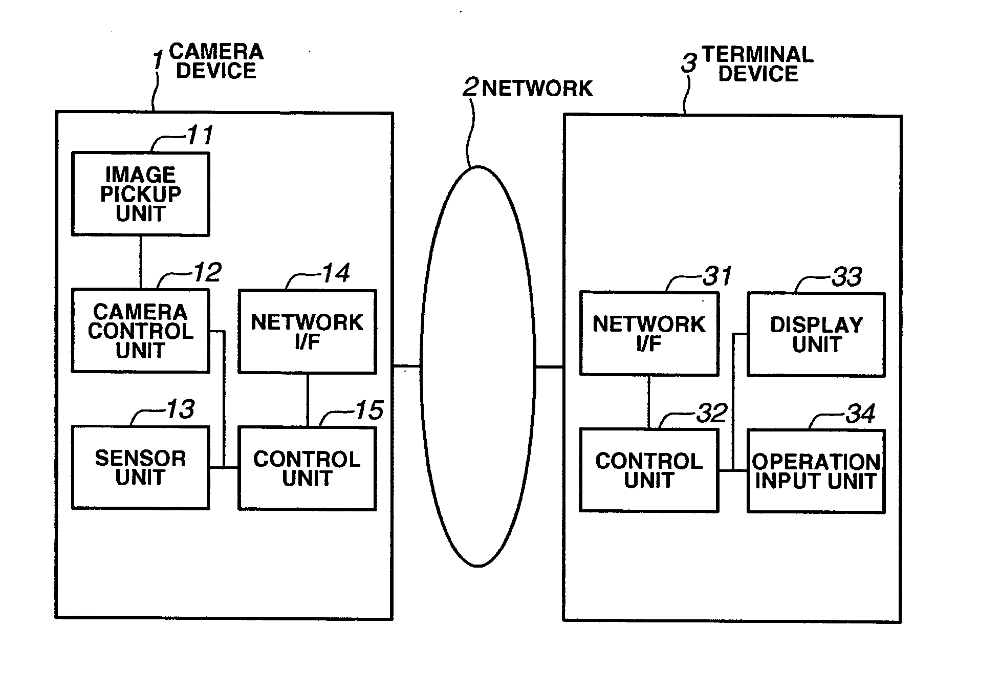
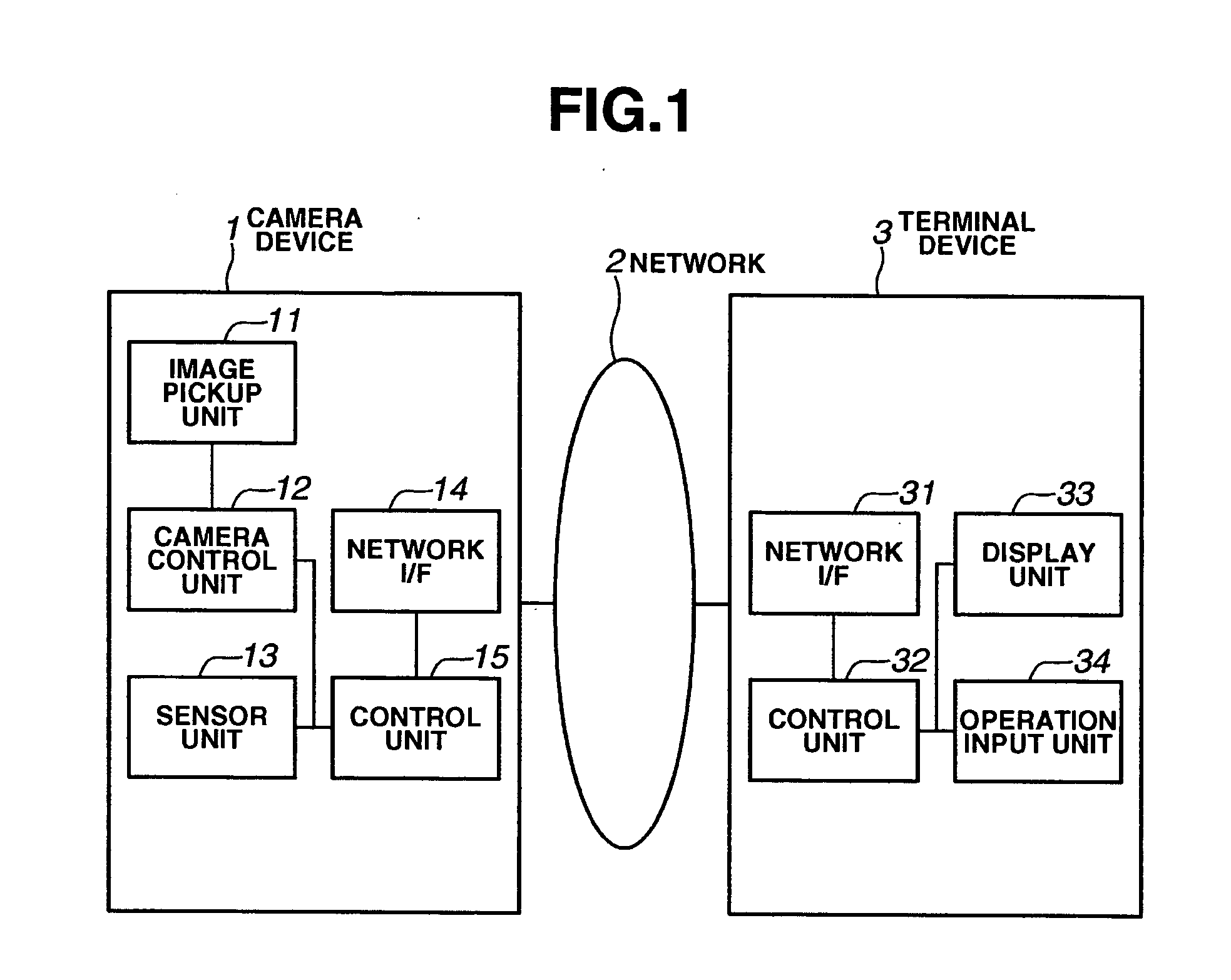
[0061]FIG. 1 is a schematic diagram that illustrates an exemplary configuration of a network camera system according to a first embodiment of the present invention. The network camera system is constituted by a camera device 1, a network 2, and a terminal device 3.

[0062] The camera device 1 includes an image pickup unit 11 that picks up an image, a camera control unit 12 that controls a direction of image taking, a zoom value, and an image taking processing, and a sensor unit 13 that detects a change of an environment in which the image taking is performed, based on a condition of light, a voice, a temperature, and the like. Further, the camera device 1 includes a control unit 15 that controls the entire camera device 1 and a network interface 14 that sends and receives data via the network 2. It is noted that the camera device 1 can change a shooting direction, which is, for example, of a slew type.

[0063] The terminal device 3 includes a display unit 33 that displays the image, a...

second exemplary embodiment

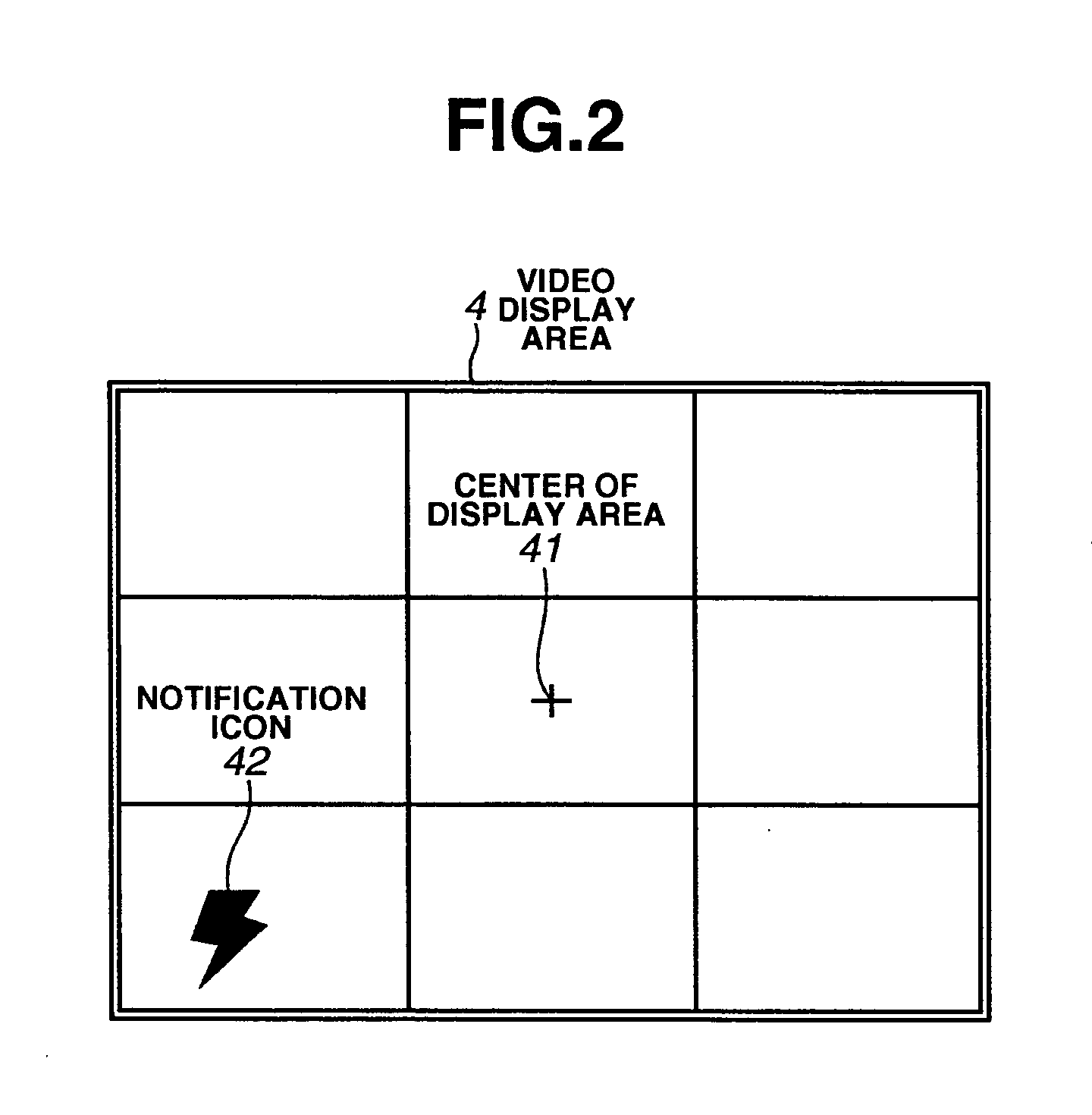
[0071] In the first embodiment, the notification icon 42 is displayed in a superposed manner. However, the embodiment of the present invention is not limited to this constitution. Instead of the notification icon 42, the images of all areas that can be photographed by the camera device 1 may be stored in advance, and the image obtained by cutting off the area where the condition change occurs may be displayed.

third exemplary embodiment

[0072] In the first embodiment and the second embodiment, the control unit 15 of the camera device 1 computes the direction of the condition change. However, the embodiment of the present invention is not limited to this constitution. Instead of the control unit 15, the terminal device 3 may compute the direction of the condition change. To be more specific, the sensor unit 13 of the camera device 1 detects the occurrence of the condition change and the position of the condition change in its peripheral. The sensor unit 13 notifies the occurrence of the condition change and the position where the condition changes, to the terminal device 3. Upon receipt of the notification of the information, the terminal device 3 computes the direction of the condition change relative to the shooting direction controlled by the camera control unit 12.


PUM


Abstract

A network camera system is provided that detects an occurrence of a condition change at a periphery of an image pickup apparatus, obtains a direction of the detected condition change, and notifies a user of the occurrence of the condition change and a direction of the condition change on a display of a terminal device.

Description

BACKGROUND OF THE INVENTION [0001] 1. Field of the Invention [0002] The present invention relates to a camera system including a camera, and in particular, relates to a network camera system that displays an image photographed by a camera using a terminal device connected via a network. [0003] 2. Description of the Related Art [0004] Conventionally, there is a network camera system that displays an image photographed by a camera using a terminal device connected via a network. In addition, there is a network camera system that displays the image on the terminal device while controlling an image taking direction of the camera through the terminal device. There is, for example, the WebView Livescope system developed by Canon, Inc. The system of this kind is utilized in a monitoring camera and a video conference system. [0005] In a conventional monitoring system, a method is employed in which the image taking direction is previously set and the camera is automatically adjusted in the p...

Claims


Application Information

Patent Timeline
IPC IPC(8): H03M7/40
CPCG08B13/196H04N5/232H04N7/183H04N5/23238H04N5/2624H04N5/23206H04N23/661H04N23/698H04N23/633H04N23/631
Inventor TAKANEZAWA, TETSUHIROOHSAWA, HIROYUKISATO, HIROSHIMATSUGU, MASAKAZUKATO, MASAMIMORI, KATSUHIKOMITARAI, YUSUKE
Owner CANON KK
Learn More