
Clamp for external fixation

a clamping jaw and external technology, applied in the field of clamping jaws, can solve the problems of high fatigue of coil springs, inaccessible coil springs, and high clamping jaws, and achieve the effect of increasing the clamping effect of the fastening

Active Publication Date: 2006-11-16
DEPUY SYNTHES PROD INC
View PDF18 Cites 61 Cited by
  • Summary
  • Abstract
  • Description
  • Claims
  • Application Information

AI Technical Summary

Benefits of technology

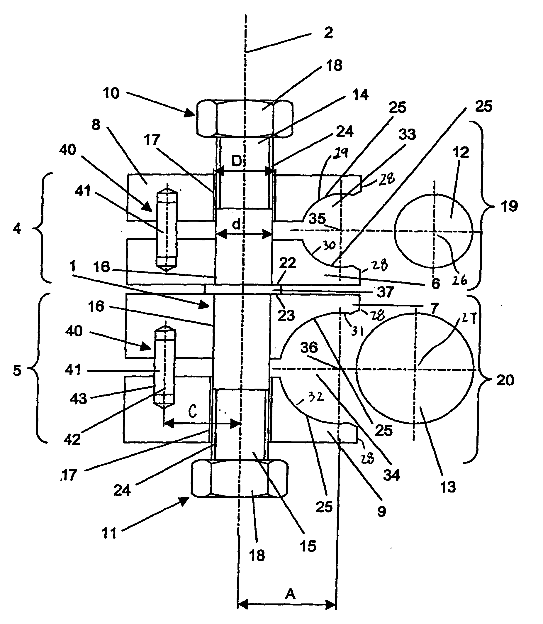
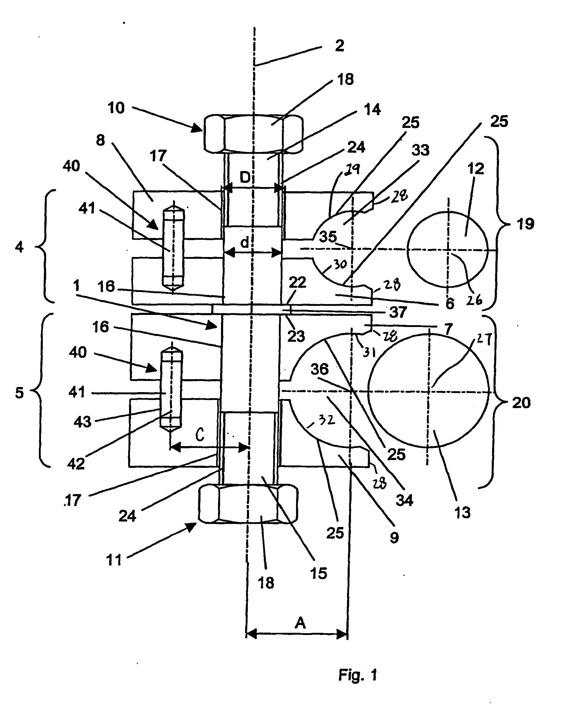
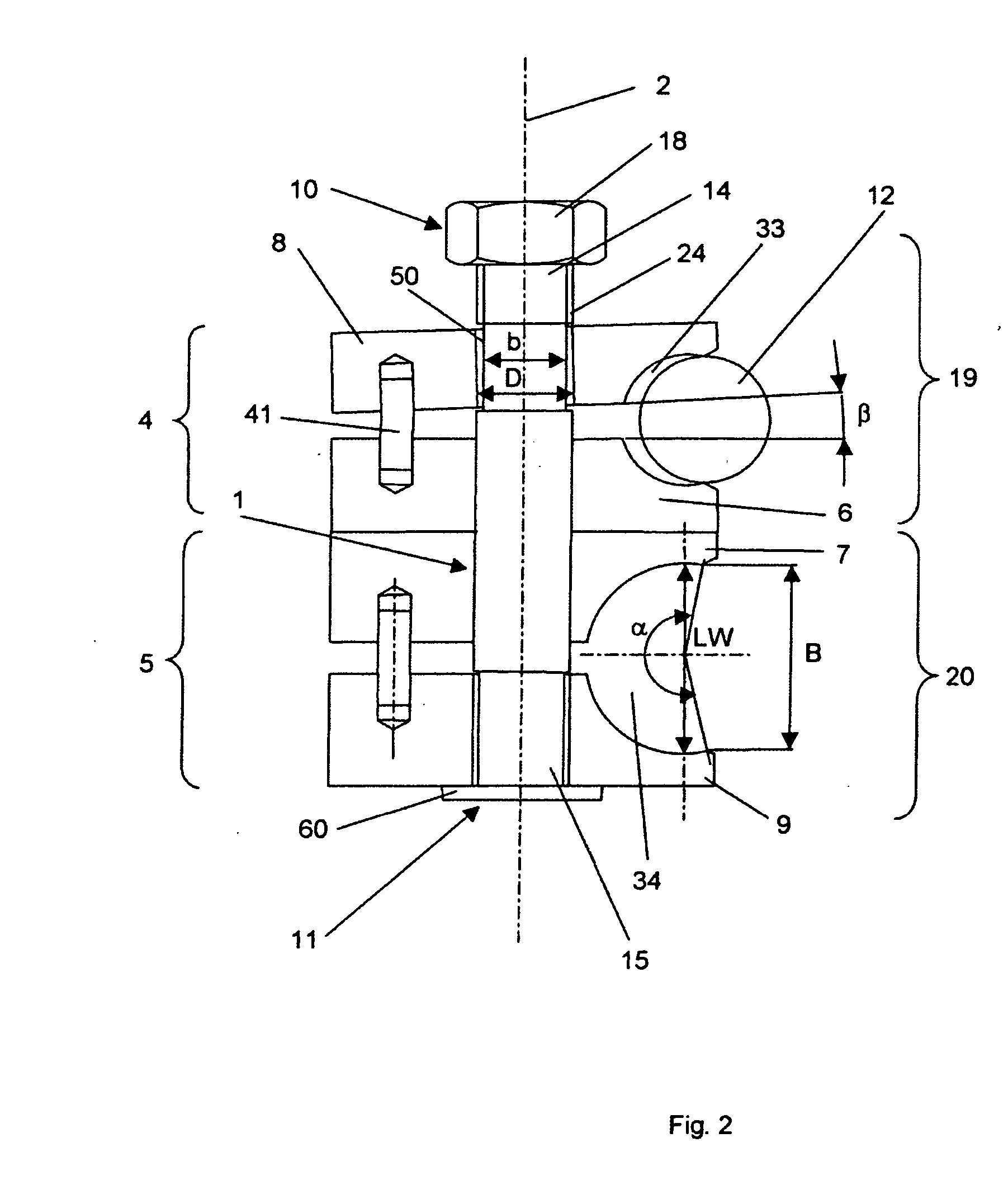
[0006] The inner and outer jaws of the first and second pair of clamping jaws may comprise clamping surfaces, wherein the inner jaw and the outer jaw of each pair of clamping surfaces may have indentations facing each other. The indentations of each pair of clamping jaws cooperate to form channels to accommodate rod-shaped fastening means such as, for example, bone pins, screws, rods, etc. There may be an increased clamping effect on the fastening means when the angle α of an arc of contact or wrap is more than about 180°. The angle α of the arc of contact or wrap defines the area of contact or interface between a fastening means and the clamping surfaces.

Problems solved by technology

One disadvantage of this construction is that the coil spring is disposed between the pairs of clamping jaws and, therefore, may not be readily accessible.
A coil spring is also subject to high fatigue.

Method used


Image

  • Clamp for external fixation
  • Clamp for external fixation
  • Clamp for external fixation

Examples


Embodiment Construction

[0017] As shown in FIG. 1, the clamping device may include a rod 1 and a pair of clamping jaws 4, 5 which may be positioned on the rod 1. The clamping jaws 4, 5 may have inner clamping jaws 6, 7, respectively, and outer clamping jaws 8, 9, respectively. It should, however, be understood that those of ordinary skill in the art will recognize many modifications and substitutions which may be made to various elements of the clamping device.

[0018] The rod 1 may have two rod segments 19, 20 and a longitudinal axis 2. The rod 1 may be a single piece of material or may have multiple pieces. The pair of clamping jaws 4, 5 may be axially displaceable on each rod segment 19, 20, respectively. The clamping jaws 6, 7, 8, 9 may be shifted axially (i.e., axially displaceable) in pairs on the rod 1 and, in particular, on rod segments 19, 20. Furthermore, the clamping jaws 6, 7 and 8, 9 may be provided with boreholes 16, 17, respectively, which may be coaxial with the longitudinal axis 2. In one e...


PUM


Abstract

A device for detachably clamping fastening elements in a surgical fixing or repositioning device. The device may a rod with a longitudinal axis. A first and second pair of clamping jaws may be operably associated with the rod. Each pair of clamping jaws may have a side surface as well as an inner clamping jaw and an outer clamping jaw, which may have indentations forming a channel. The channels may be opened towards the side surface of the clamping jaws. A fastening means may be positioned in the channels by pushing the fastening means into the openings in the side surface in a direction which may be at an angle with respect to the longitudinal axis of the rod. An elastic element may be positioned between the inner and outer clamping jaws of at least one pair of clamping jaws so as to resist movement of the inner and outer clamping jaws with respect to each other as a fastening means is inserted therebetween. A clamping element may engage the rod and may be used to fix the orientation of the clamping jaws and fastening means with respect to each other.

Description

CROSS-REFERENCE TO RELATED APPLICATION [0001] This application is a continuation of pending International Patent Application PCT / CH2003 / 000424, filed Jun. 26, 2003, which is incorporated by reference herein in its entirety.FIELD OF THE INVENTION [0002] The present invention relates to a clamp for external fixation and, more particularly, to a device for detachably clamping fastening elements in a surgical fixing or repositioning device. BACKGROUND OF THE INVENTION [0003] A double jaw connection for elements of an external fixator is known in the art. For example, DE 295 12 917 to Jaquet shows a layered arrangement of two pairs of clamping jaws, which consists of an upper outer clamping jaw and an upper inner clamping jaw, as well as a lower outer clamping jaw and a lower inner clamping jaw. The four clamping jaws are disposed on a central clamping shaft. Between the pairs of clamping jaws, that is, between the two inner clamping jaws, a coil spring is inserted. The coil spring cause...

Claims


Application Information

Patent Timeline
Patent Type & Authority Applications(United States)
IPC IPC(8): B25B1/00A61B17/64
CPCA61B17/6466A61B17/645
Inventor BRUNNER, PETERFUHRER, MARCEL
Owner DEPUY SYNTHES PROD INC
Learn More