Insulator apparatus for vacuum insulated tubing

a technology of vacuum insulation and insulation apparatus, which is applied in the direction of mechanical equipment, sleeve/socket joints, drilling pipes, etc., can solve the problems of reducing well productivity, frequent subject to damage, and proportional increase in fluid viscosity

Inactive Publication Date: 2006-11-16
FORUM US
View PDF17 Cites 0 Cited by
  • Summary
  • Abstract
  • Description
  • Claims
  • Application Information

AI Technical Summary

Benefits of technology

[0013] The present invention provides an insulator apparatus for use with vacuum insulated tubing strings, where the apparatus includes an insulator adapted to insulate joints in the vacuum insulating tubing string and a joint protector adapted to secure the insulator against the joints, to protect the joints from damage during run in and run out and to provide a protected conduit adapted to receive injection or control tubing associated with the vacuum insulated tubing.
[0017] The present invention provides an apparatus including an insulator adapted to conform to the outer contour of the joint and a portion of the tubing on either side of the joint and a protector including a pair of half-cylinder shaped sections which are interconnected at respective edges by an elongate piano-type hinge having a releasable pin. The opposite edges are provided with a plurality of pin guide sections matingly received by each other to define a pair of longitudinal pin slots when the protector is disposed about a tool joint. A pair of mating tapered pins are provided for each slot whereby when the pins are driven into their respective slots, the edges of the half-sections carrying the pin guides are drawn toward each other to effect progressively tighter engagement of the protector about the tool joint and tubing in an interference fit. Half-sections of varying radii of curvature and pins of varying taper are provided, whereby a variety of tool joints having differing outer dimensions may be accommodated, resulting in an effective interference fit by substituting half-sections and pins of appropriate size. A window intermediate the pair of pin slots facilitates lower pin installation while providing for slight flexing of the protector about the tool joint to further accommodate dimensional variations thereof.

Problems solved by technology

One problem with these tool joints and the associated tubing or cables (referred to hereinafter as tubing for convenience) is that they are frequently subjected to damage from contact with surrounding casing or the formation itself, such as when the production string is moved up or down within the borehole.
This damage may be due to abrasion or compressive forces against the joint or tubing which often occurs as the tool joint is moved across a deviation in the borehole.
In deep water drilling operations, one difficulty in producing oil from such deep wells is the loss of heat associated with the oil as it flows out of the productive formation into the production tubing resulting in proportional increase in fluid viscosity and reduced well productivity.
However, heat loss is still a problem at the joints of the tubing where, out of necessity, the joints are not insulated and therefore heat can flow out of the joints to the surrounding.

Method used


Image

  • Insulator apparatus for vacuum insulated tubing
  • Insulator apparatus for vacuum insulated tubing
  • Insulator apparatus for vacuum insulated tubing

Examples


Embodiment Construction

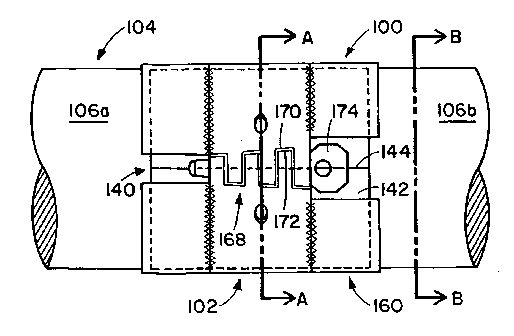
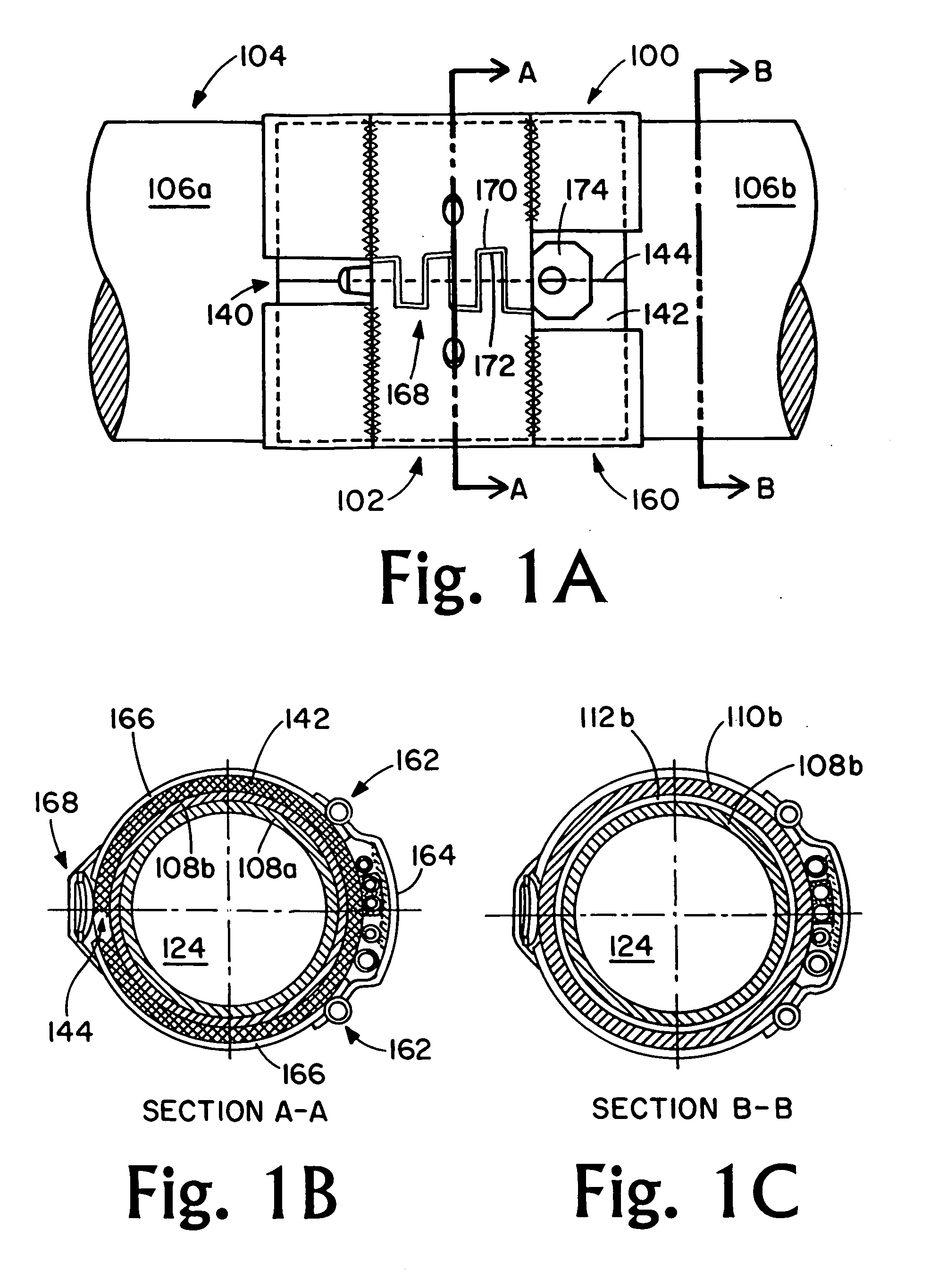
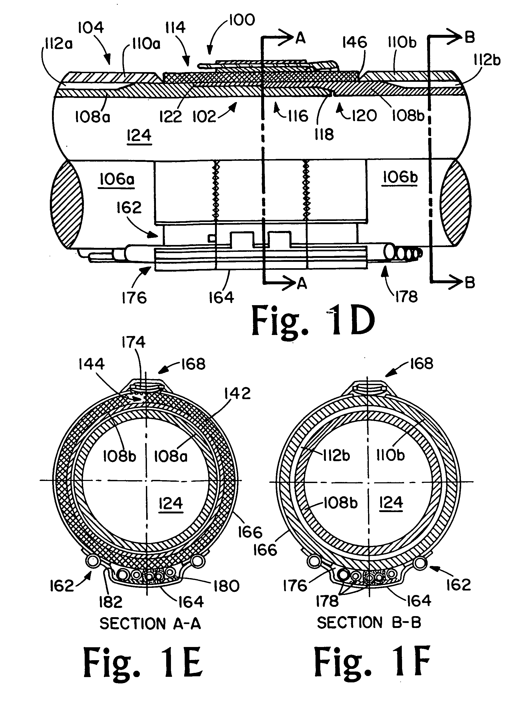
[0026] The inventors have found that heat loss from joints of a vacuum insulated tubing string can be reduced by as must as 95% or more by detachably affixing to each joint an insulating apparatus including an insulator adapted to conform to an outer surface of the joint and preferably to conform to a portion of the tubing on either side of each joint and a joint / insulator protector adapted to be interference fit to the tubing on either side of each joint, to secure the insulator in place and to provide a protected conduit for injection and control tubing. Thus, the inventors have found that a vacuum insulated tubing string can be formed including an insulator protector of this invention associate with each joint in the string reducing heat loss through the joints by as much as 95%.

[0027] The present invention broadly relates an insulator apparatus for use with vacuum insulated tubing strings, where the apparatus includes an insulator adapted to insulate joints in the vacuum insula...


PUM


Abstract

An insulating apparatus for use with vacuum insulated tubing sting to reduce heat loss through the joints, where the apparatus includes an insulator adapted to surround the joint and a latching joint protector adapted to surround the insulator and hold the insulator against the joint, where the protector also includes a channel for receiving injection and / or control tubing. The insulator is capable of reducing heat loss through the joints of a vacuum insulated tubing string by as much as 95%.

Description

RELATED APPLICATION [0001] This application is a continuation application to U.S. patent application Ser. No. 10 / 744,575, filed 22 Dec. 2003, which claims the benefit of provisional priority to U.S. Provisional Patent Application Ser. No. 60 / 434,903 filed 20 Dec. 2002.BACKGROUND OF THE INVENTION [0002] 1. Field of the Invention [0003] The present invention relates to an insulator apparatus for vacuum insulating tubing. [0004] More particularly, the present invention relates to an insulator apparatus for vacuum insulating tubing adapted to provide insulation at joints in a vacuum insulating tubing string including an insulating member and a joint protector surrounding and holding the member in place at the joints. [0005] 2. Description of the Related Art [0006] In the petroleum industry, production tubing is disposed within a borehole for transporting oil and gas from subsurface bearing formations to the surface. This tubing is comprised of elongate sections threaded together to form...

Claims


Application Information

Patent Timeline
Patent Type & Authority Applications(United States)
IPC IPC(8): F16L9/14F16L59/02
CPCF16L59/022
Inventor HICKMAN, COLE J.CANNON, JAMES H.
Owner FORUM US
Why Eureka
Try Eureka