
Graphical user interface (GUI) based call application system

a call application system and graphical user interface technology, applied in the field of communication systems, can solve the problems of inaccurate billing of customers, high human resources, and inability to meet the requirements of customers,

Active Publication Date: 2006-11-09
VERIZON PATENT & LICENSING INC
View PDF16 Cites 18 Cited by
  • Summary
  • Abstract
  • Description
  • Claims
  • Application Information

AI Technical Summary

Benefits of technology

The present invention provides a call application system that allows customers to create, review, and modify call plan applications in real-time through a web-based graphical user interface. The system supports a wide range of features, including audio play, database access, and call extension. The invention also includes a method for providing self-service call plan application development, a system for automated creation and deployment of call plan applications, and a computer-readable medium carrying instructions for providing self-service call plan application development. The technical effects of the invention include improved efficiency and flexibility in call plan development, as well as improved user experience and operational efficiency.

Problems solved by technology

A drawback of this traditional approach is that the approach is costly in terms of human resources.
Another drawback is that this process is prone to errors and inaccuracies in implementing the requirements of the customer.
These errors may also be introduced in the billing process, resulting in inaccurate billing of the customer.
Yet another drawback of the conventional system is that delays and inefficiencies attend a manual process; that is, there is delay between submission of the call plan and deployment.
Additionally, any testing and re-testing of the call plan application further adds to the delay.
Conventional representations of call plans are not suitable for customer display, as the customer is unnecessarily exposed to too much implementation details.
Additionally, conventional systems lack information (e.g., message text) that is needed by the customers.
Conventional application profiles are text-based, free-format, making automated conversion into a graphical format unfeasible.

Method used


Image

  • Graphical user interface (GUI) based call application system
  • Graphical user interface (GUI) based call application system
  • Graphical user interface (GUI) based call application system

Examples


Embodiment Construction

[0032] In the following description, for the purposes of explanation, numerous specific details are set forth in order to provide a thorough understanding of the present invention. It is apparent, however, to one skilled in the art that the present invention may be practiced without these specific details or with an equivalent arrangement. In other instances, well-known structures and devices are shown in block diagram form in order to avoid unnecessarily obscuring the present invention.

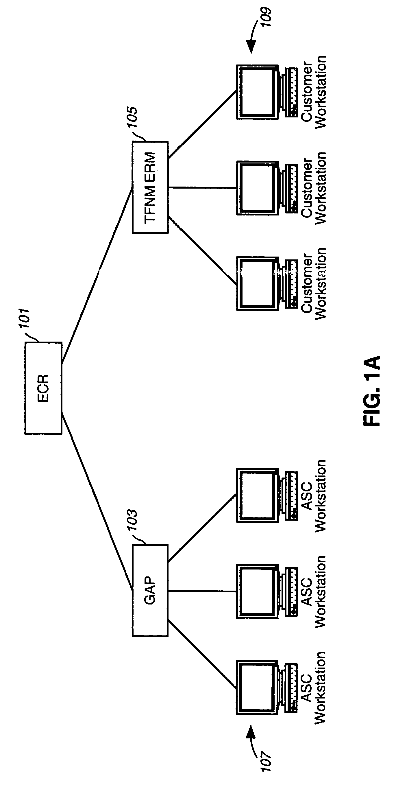
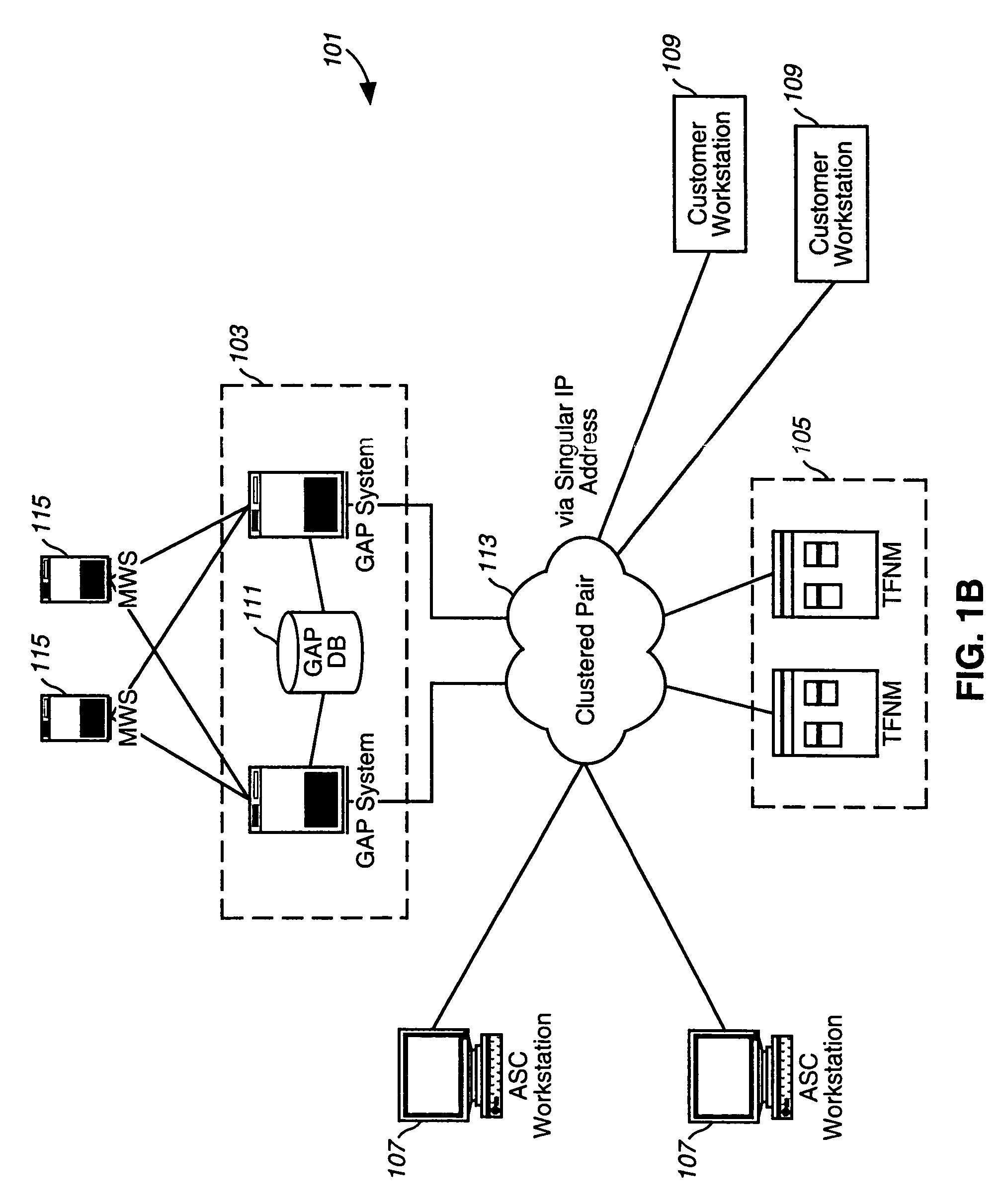
[0033] The present invention provides a graphical approach for customers (i.e., subscriber of a service) of a service provider to create call plan applications. The graphical system provides a “self-managed” and automated service from the perspective of the customer. The graphical system supports automated creation of call plans, whereby the graphical user interfaces (GUIs) are utilized to create a graphical, logical representation of the call plan. This representation is then used to automatically ...


PUM


Abstract

An approach for providing self-service call plan application development is disclosed. A graphical system includes a computing system that is configured to cause a graphical user interface (GUI) to be present for automated creation of an application for controlling call flow logic. The application supports a predefined feature set. Additionally, the system includes a database that is coupled to the server and configured to store the application. The server is further configured to determine whether the application is valid and to initiate deployment of the application. The deployment may be performed on a real-time basis.

Description

FIELD OF THE INVENTION [0001] The present invention relates to a communications system and more particularly to graphical system for developing call applications. BACKGROUND OF THE INVENTION [0002] As telecommunication technologies continue to advance, the sophistication of the customers of telecommunication services is increasing. The commercial sector has become reliant on the telecommunication service providers to supply call services (e.g., call centers, interactive voice response (IVR) platforms, etc.) with the flexibility to adapt to continually changing requirements. Sophisticated customers demand that they be given more control over their services, particularly with the prevalence of global networks (such as the Internet) to facility access to the necessary resources to self-manage the services. In addition, these customers require a wide range and robust set of features relating to the call services. [0003] Conventionally, service providers offer managed telecommunication s...

Claims


Application Information

Patent Timeline
Patent Type & Authority Applications(United States)
IPC IPC(8): G06F3/00H04M3/51G06F17/50H04M3/42H04M3/493H04Q3/00
CPCG06F30/00G06F2111/02H04M2203/355
Inventor COBB, DALEGILBERT, PAULSANTA, PHYLLIS
Owner VERIZON PATENT & LICENSING INC
Learn More