
High intensity light arrangement and method

a high-intensity, light-emitting technology, applied in the field of light-emitting arrangement, can solve the problems of inability to dim incandescent bulbs, inability to dim fluorescent bulbs, and inability to achieve uniform and high-intensity light-emitting effects

Inactive Publication Date: 2006-11-09
WECHSLER LAWRENCE I
View PDF2 Cites 0 Cited by
  • Summary
  • Abstract
  • Description
  • Claims
  • Application Information

AI Technical Summary

Benefits of technology

[0014] While virtually any light source can be used in the above described arrangements, use of compact fluorescent light elements is considered particularly advantageous, at present, since each light can be selected to emit a desired spectrum and intensity of light for a given application. Additionally, since each light has its own ballast, the fixture using such lights is, itself, advantageously light weight, maintenance-free, and lights of different wattage can be freely substituted without requiring a change in ballast, as would be otherwise required in a fixture utilizing standard fluorescent bulbs. However, it is contemplated that other light sources may be developed in the future, and the invention is intended to apply to the use of these new lights elements.

Problems solved by technology

For example, incandescent bulbs can be dimmed, but are the least light efficient, generating greater heat and less light per watt consumed than the remaining type lamps.
Fluorescent bulbs, while having greater efficiency than incandescent bulbs, cannot be dimmed.
While fluorescent lights, which are readily available and relatively inexpensive to buy and operate, and which output light in a spectral range usable in photosynthesis, they have heretofore not generally not been utilized in a manner which can provide a sufficient level of light required by many plants and simulated reef environments.
However, a light fixture and / or light arrangement, employing these and / or other type light elements (conventional and those yet to be developed), emitting similar or more intense light, has heretofore not delivered a suitable intensity of light for many applications, particularly for use in growing plants, such as cactus and succulents, which have high light requirements in the range of 20,000 lux and above.

Method used


Image

  • High intensity light arrangement and method
  • High intensity light arrangement and method
  • High intensity light arrangement and method

Examples


Embodiment Construction

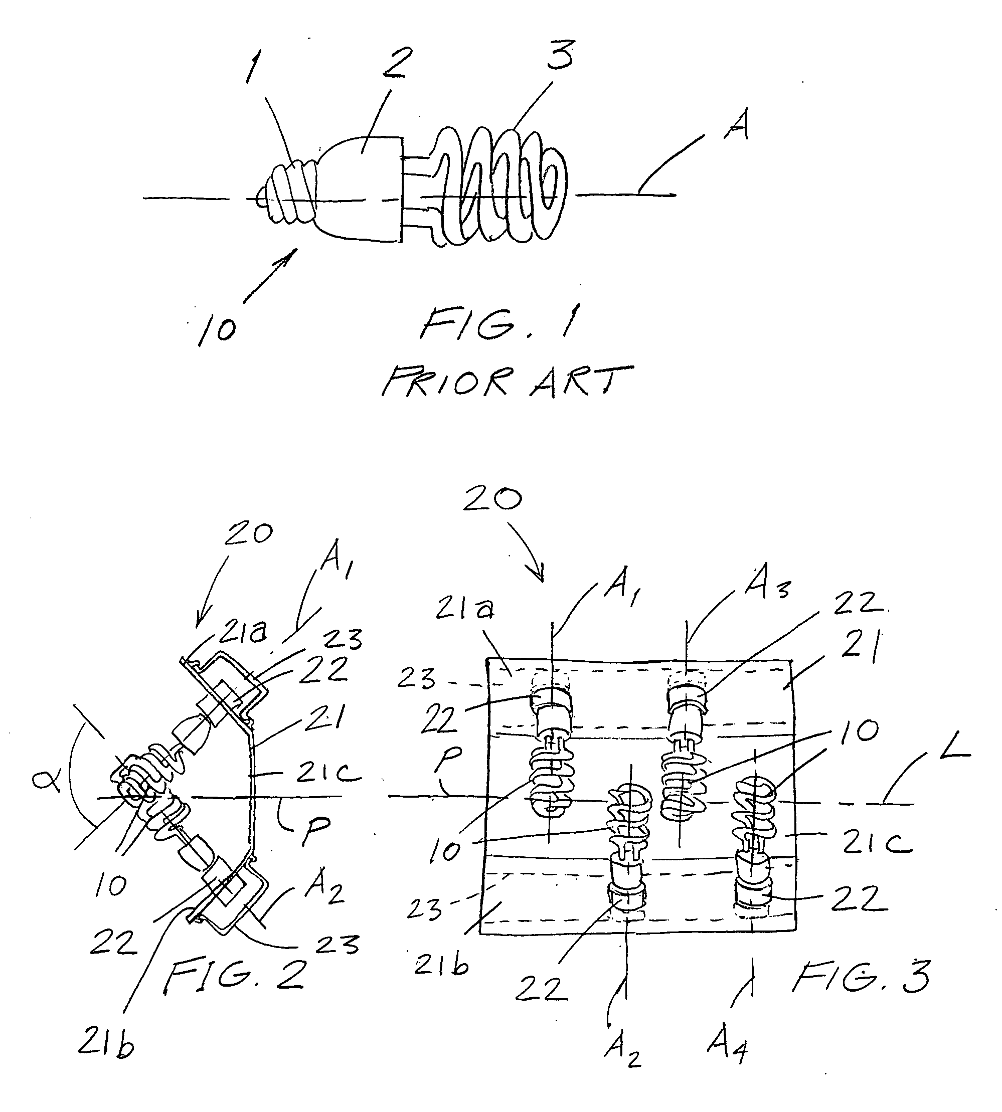
[0023] Referring now to the figures, and in particular FIG. 1, a conventional compact fluorescent light element is shown at 10. Light element 10 includes a screw base 1, a ballast housing 2 and a spiral light emitting portion 3 (which is also sometimes of a shape other than spiral, and which is not depicted, yet also equally suitable for use in connection with the disclosed invention), all arranged sequentially in a direction of an orientation axis A and disposed in respective axial positions therealong.

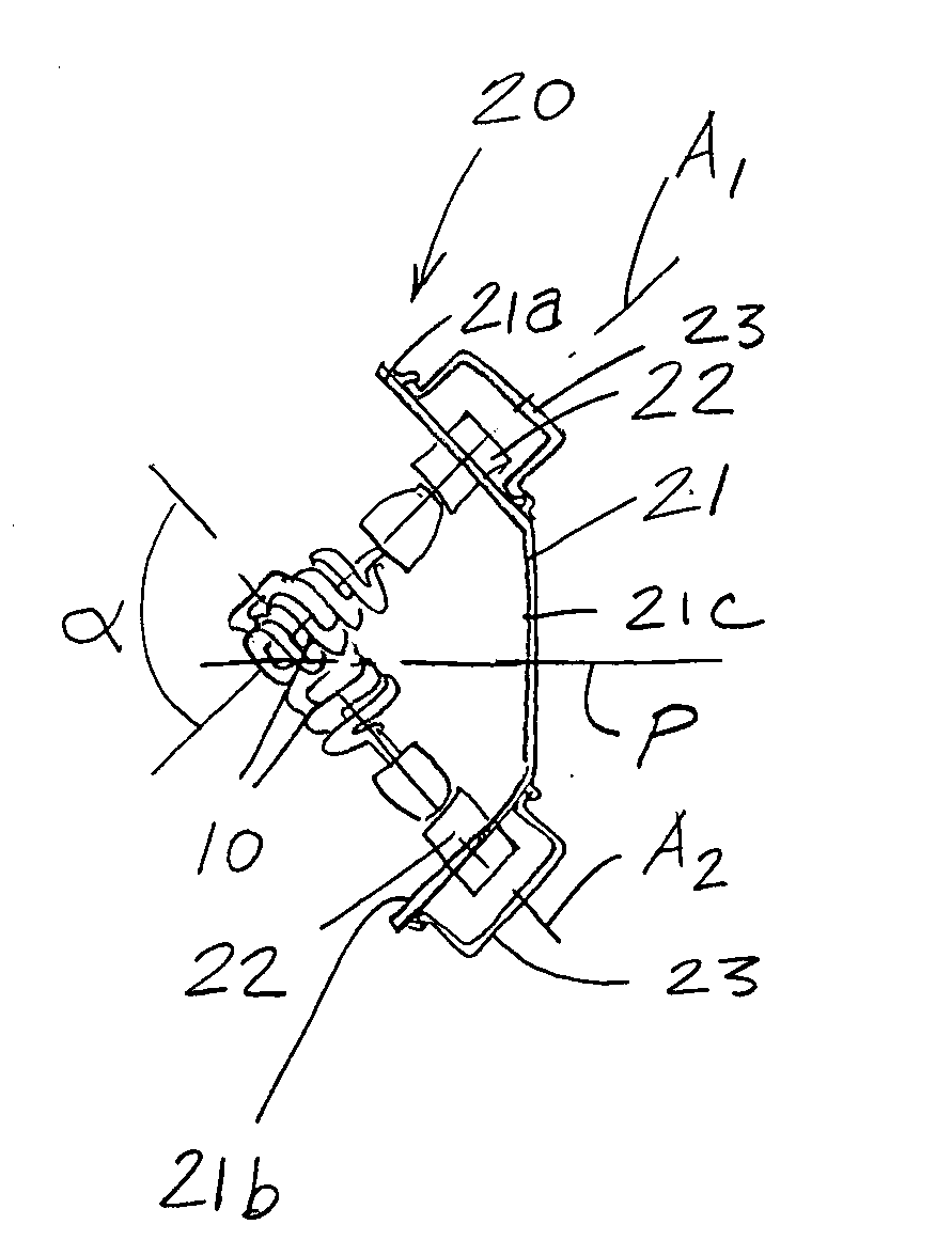
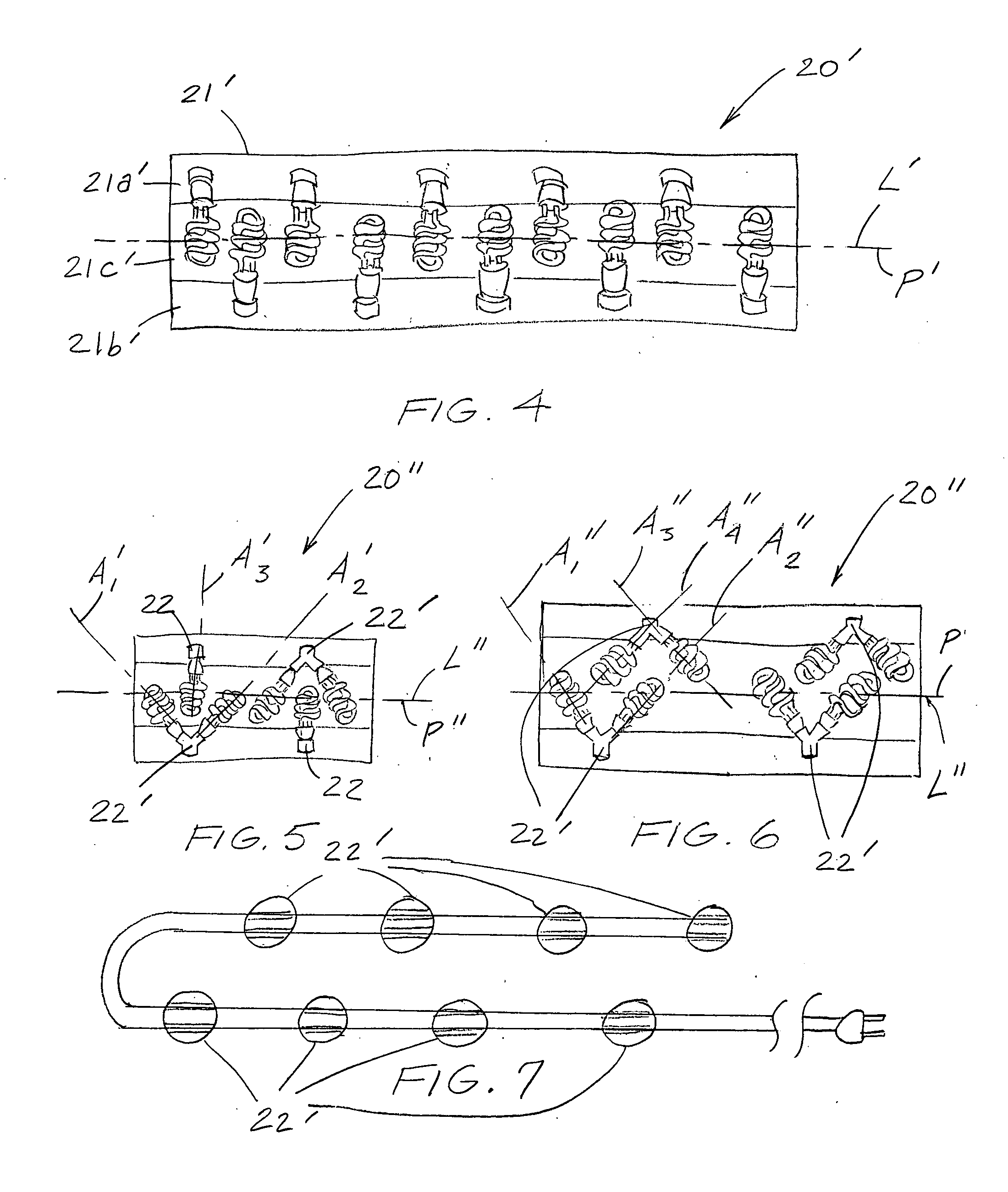
[0024] Turning to FIGS. 2 and 3, an embodiment of a light arrangement is shown, generally designated 20. Light arrangement 20 is provided as a combination of elements including a housing 21, light sockets 22 and light elements 10 received therein. Housing 21 is conveniently constructed of a rigid material, for example, bent sheet steel, of similar construction, for example, as standard shop fixture reflectors. Housing 21 is advantageously bent to form a generally trapezoidal shape i...


PUM


Abstract

A light a light arrangement employs at least one support extending in a length direction along an arrangement axis, to which individual light bulbs are mountably receivable in ordered fashion. The lights are of the type having an orientation axis, along which a base and a light emitting portion are disposed in respective axial positions. When installed to the support, the lights are energizable from a power source to emit light in a desired direction, for example, downward, when in a use orientation. To achieve the desired characteristics, at least a portion of the lights are laterally arranged on one side of the arrangement axis and a remaining portion arranged on the opposite side of the arrangement axis, the lights being positioned such that the orientation axes of the light elements run crosswise to the arrangement axis of the support to which they are received.

Description

CROSS REFERENCE TO RELATED APPLICATIONS [0001] This application claims the benefit of U.S. Provisional Application No. 60 / 660,106 filed Mar. 9, 2005 entitled HIGH INTENSITY LIGHT ARRANGEMENT AND METHOD.BACKGROUND OF THE INVENTION [0002] The present invention relates to a light arrangement, and more particularly to a light arrangement suited for use in lighting an area, including one of elongated linear dimension, such as, for example, for disposition over a plant bench in the home or a conservatory, and which can provide light of greater intensity than many conventional fixtures, and a method of providing such lighting. [0003] Many types of light fixtures are available for providing artificial light in connection with a number of diverse activities. These conventionally use various types of light sources, including incandescent, fluorescent, metal halide and sodium lamps. Each of these light sources have particular advantage and disadvantage, and selection of a particular type is de...

Claims


Application Information

Patent Timeline
IPC IPC(8): F21V21/00F21V19/00
CPCA01G9/26A01K63/06F21Y2111/00F21S4/001F21Y2103/02F21S4/00F21S4/10F21Y2103/30A01G9/249Y02A40/25
Inventor WECHSLER, LAWRENCE I.
Owner WECHSLER LAWRENCE I
Learn More