
Robotically Assisted Launch/Capture Platform For An Unmanned Air Vehicle

a technology for air vehicles and robotics, applied in the field of robotic assisted launch/capture platforms for unmanned air vehicles, can solve the problems of uavs having to be captured and stabilized within a very limited space, ship-based mission platforms presenting more challenging environments, and high instability of vessel platforms

Inactive Publication Date: 2006-11-09
LOCKHEED MARTIN CORP
View PDF17 Cites 148 Cited by
  • Summary
  • Abstract
  • Description
  • Claims
  • Application Information

AI Technical Summary

Benefits of technology

[0011] An embodiment of the invention is directed to a platform for launching and/or capturing an unmanned air vehicle (UAV), particularly a small UAV. As used herein, the term “small UAV” refers to a fixed wing unmanned air vehicle having a weight ranging from approximately 10 lbs to 300 lbs, and nominally weighing about 100 lbs or less. The launch/capture platform includes a frame, a floor attached to the frame that is capable of supporting the UAV, means for acquiring and tracking the UAV in flight, a connector and a connector controller, connecting the platform to an external support structure, providing a controllable, adaptive motion of the platform in response to approaching UAV position and attitude, means for launching the UAV from the platform and for capturing an in-flight UAV to the platform, and means for locking down the UAV between the capture and launch of the UAV. In a particular aspect, the external support structure to which the platform is controllably connected is a controllable robotic arm having a base at one end for secure attachment to a host platform and attached to the platform at another end thereof via the controllable connector. According to an aspect, the frame of the platform has a base member and two arm members extending transversely from respective end regions of the base member to form a generally squared U-shaped structure. According to an aspect, the means for launching the UAV from the platform and capturing an in-flight UAV to the platform build upon known “ar...

Problems solved by technology

The ship-based mission platforms present the more challenging environments, particularly for capturing an in-flight UAV.
Vessel platforms can be highly unstable due to rolling, pitching and yawing and other unpredictable movements of the vessel in choppy water as well as to forward motion.
In addition, small, fixed-wing UAVs on the order of 10 to 300 pounds, and nominally about 100 pounds, are highly vulnerable to airwake turbulence from the vessel superstructure and prevailing winds, and the UAV may have to be captured and stabilized within a very limited space on an already crowded deck.
Both capture system approaches are known to induce high probabilities of UAV damage.
Both the weight and the wing span of the UAV being captured can significantly impact these types of capture systems.
This requirement may significantly intrude on shipboard structures and deck operations.
Attitude and UAV course errors that result in non-perpendicular initial contact with the net can snag a wingtip thus resulting in inertial forces being magnified in proportion to wing length and subsequent wing damage.
The risk of damage may be compounded by subsequent buffeting while the UAV is captured within the net and exposed to prevailing or platform velocity-produced winds.
They also place constraints on the bearing and speed of the ship based capture structure.
Furthermore, these types of systems cannot be used to launch the UAV, thus a separate launch system is required.
Although a mobile system may address certain of these issues, even small UAVs may generate significant inertial forces during launch acceleration and retrieval deceleration, requiring a platform having inertial stability, at odds with adaptable mobility.

Method used


Image

  • Robotically Assisted Launch/Capture Platform For An Unmanned Air Vehicle
  • Robotically Assisted Launch/Capture Platform For An Unmanned Air Vehicle
  • Robotically Assisted Launch/Capture Platform For An Unmanned Air Vehicle

Examples


Embodiment Construction

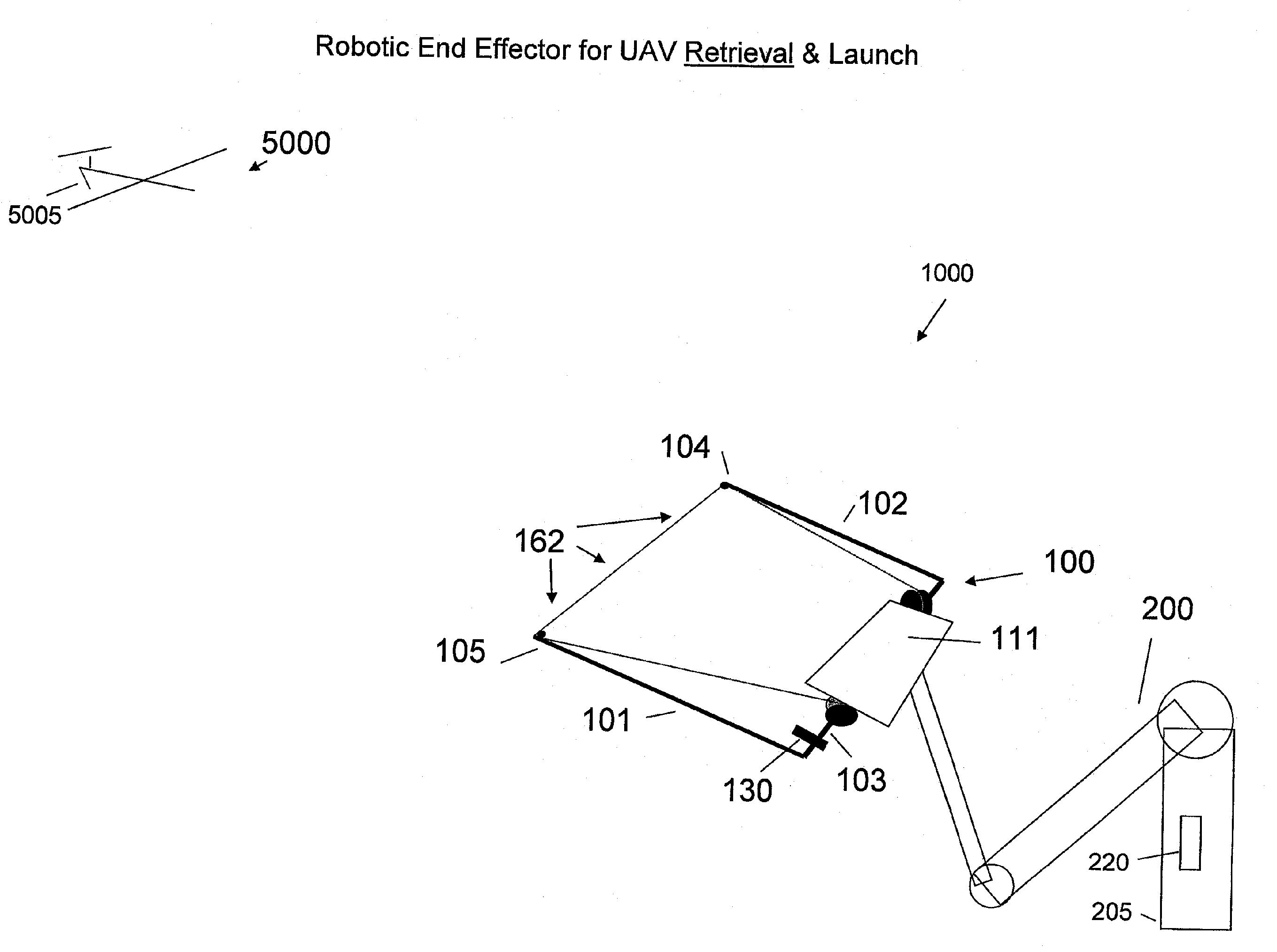
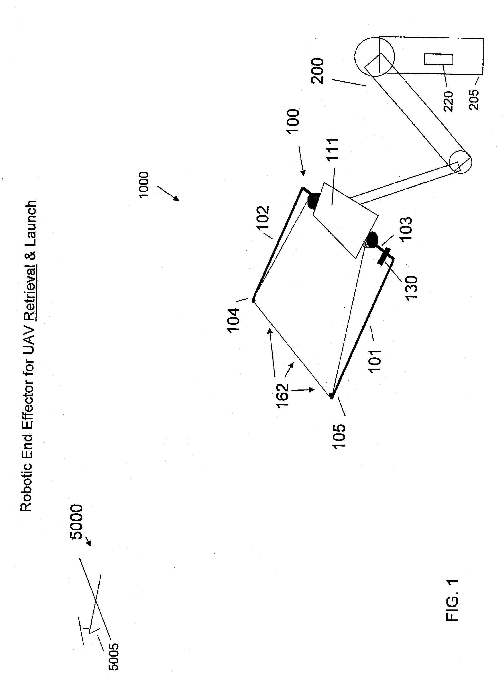
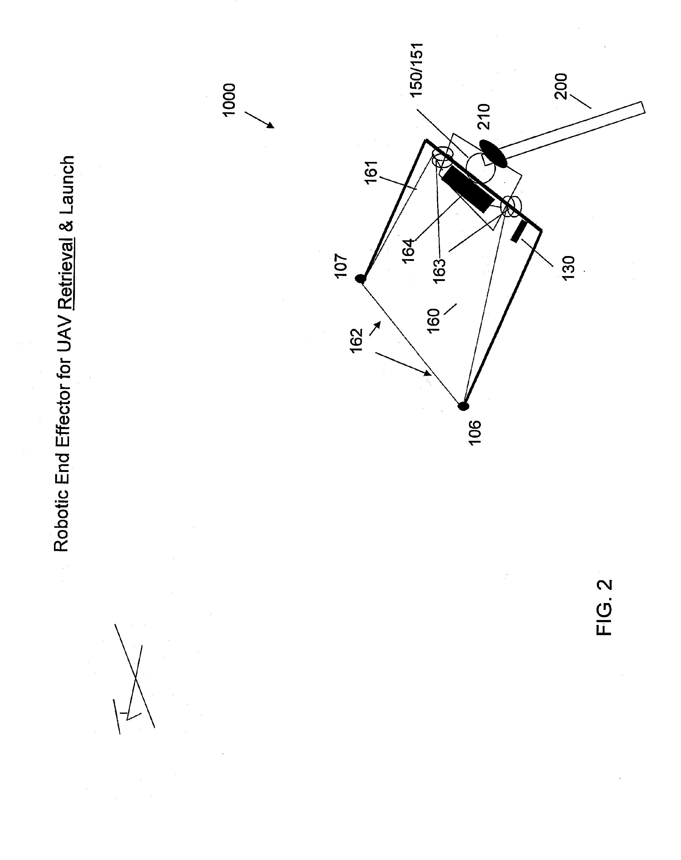
[0022] An embodiment of a launch / capture platform 1000 for a small unmanned air vehicle (UAV) 5000 is illustrated with reference to FIGS. 1 and 2. The platform 1000 includes a frame 100 having a pair of arm members 101, 102 extending transversely from a base member 103 of the frame. Each of the arm members 101, 102 has a free end 105, 104, respectively. The arm members can be of varying length and, in an exemplary aspect, extend from the base member on the order of about 12 feet. Shorter or longer arm lengths may be used and can be selected based upon a variety of factors that will be clearly understood by a person skilled in the art based on the disclosure described herein below. It is advantageous if the platform 1000 can be made to be rapidly maneuverable and also strong enough to handle the inertial forces generated by capturing and launching a small UAV weighing up to 300 pounds. Thus, suitable materials for the frame include fiberglass, carbon fiber, fiber composites, aluminum...


PUM


Abstract

An embodiment of the invention is directed to a platform for launching and / or capturing an unmanned air vehicle (UAV), particularly a small UAV. The launch / capture platform includes a frame, a floor attached to the frame that is capable of supporting the UAV, means for acquiring and tracking the UAV in flight, a connector and a connector controller, connecting the platform to an external support structure, providing a controllable, adaptive motion of the platform in response to approaching UAV position and attitude, means for launching the UAV from the platform and for capturing an in-flight UAV to the platform, and means for locking down the UAV between the capture and launch of the UAV. Another embodiment of the invention directed to a method for capturing a small, in-flight UAV involves providing a UAV capture platform, providing a UAV capturing means as an integrated component of the platform, providing means for determining in real-time the relative location of an engaging portion of the capturing means with respect to an approaching in-flight UAV, providing means for automatically maneuvering the engaging portion of the capturing means with respect to at least one of a position and an attitude of the approaching in-flight UAV, capturing the UAV, and securing the captured UAV to the capture platform.

Description

RELATED APPLICATION DATA [0001] This application is related to U.S. application Ser. No. ______ entitled autonomous environmental control system and method for post-capture and pre-launch management of an unmanned air vehicle, filed concurrently herewith and incorporated by reference herein in its entirety to the fullest allowable extent.DESCRIPTION [0002] 1. Field of the Invention [0003] Embodiments of the invention pertain to the control of an unmanned air vehicle (UAV) and, more particularly, to a robotically assisted launch / capture platform for a small UAV. [0004] 2. Background of the Invention [0005] The use of UAVs to conduct surveillance or fly other payload missions in remote and / or hostile environments or under dangerous conditions has significant benefits. The most obvious of these benefits is the avoidance of human exposure to these environments. Other benefits derive from the ability to equip a UAV with data collection instruments and sensors that provide the capability ...

Claims


Application Information

Patent Timeline
IPC IPC(8): B64F1/12
CPCB64F1/02B64C2201/182B64F1/04B64F1/0297B64F1/029B64U70/30B64F1/00B64F1/12
Inventor STEELE, DANIEL W.
Owner LOCKHEED MARTIN CORP
Learn More