
Apparatus and method for test and debug of a processor/core having advanced power management

a technology of advanced power management and apparatus, applied in the field of apparatus and methods for testing and debugging of processors/cores with advanced power management, can solve the problems of requiring its own tms control signal, parallel solution also does not facilitate co-emulation, and the solution of multiple taps is not conveniently scalabl

Active Publication Date: 2006-11-02
TEXAS INSTR INC
View PDF13 Cites 37 Cited by
  • Summary
  • Abstract
  • Description
  • Claims
  • Application Information

AI Technical Summary

Benefits of technology

The present invention provides an interface unit between a plurality of TAP units of processor / cores on a substrate and a test and debug unit. The interface unit includes a TAP unit and a logic unit that provides control signals for the state machine associated with each processor / core. The interface unit can also apply a sleep-inhibit signal to prevent the processor / core from entering a lower power state. The interface unit also includes status registers identifying the status of parameters in each related processor / core, which can be transmitted to the test and debug apparatus through the TAP unit and can identify whether the processor / core described by the parameters is in a state for testing. The interface unit can force the state machine into an appropriate state for testing the processor / core if it is not in a state suitable for testing. The technical effects of the invention include improved testing and debugging of processor / cores on a substrate.

Problems solved by technology

The problem with a parallel configuration is that each TAP requires its own TMS control signal.
This solution to the problem of multiple TAPS is not conveniently scalable.
Since only one TAP can drive its TDO output at the same time, the parallel solution also does not facilitate co-emulation in which multiple TAPs need to be driven through the TAP state machine at the same time.
However, once a TAP becomes inactive, there is no way for a controller to wakeup the module and re-enable scans.
There are several problems with the series test configuration.
First, if the power is removed from one TAP in the series, then the controller will be unable to shift data into and out of any TAP linked in series with the un-powered TAP.
Once a TAP has been un-powered, the scan controller is not able to wakeup the sleeping module.
The second problem is that all TAPs must be clocked at the same frequency.
Synthesizable ARM processors from ARM Ltd exacerbate this problem since the JTAG TCK (test clock) clock signal must be synchronized with the ARM processor functional clock.
Therefore, if the ARM clock is running at a slow frequency or is turned off, scanning through any of the TAPs in series with this core is not possible.
Another problem with the series configuration of TAPs is that to access one particular TAP, the controller must scan through all of the TAPs in the series.
This feature makes scaling difficult.
This complexity leads to a scan path that is thousands of bits long.
A long scan path significantly slows debug of a selected processor core.
The series configuration also presents problems for production testing.
Gating the TCLK signals presents several problems.
This unsophisticated technique does not allow for visibility in the protected system while blocking visibility into other systems.
Even if the TCLK signal was gated closer to the processor / core's TAP, this implementation would not help because the TAPs are connected in series.
The second problem is that blocking visibility into the system is in direct conflict with the needs of debug procedures that seek to give full visibility into the system.
One of the problems that can arise in the test and debug of processor / cores having advanced power management systems is the change of power, either by slowing the clock in all of parts of the processor / core or by changing the power in all or parts of the processor / core.
This change in power can result in a processor / core that can not be tested by the test and debug unit.

Method used


Image

  • Apparatus and method for test and debug of a processor/core having advanced power management
  • Apparatus and method for test and debug of a processor/core having advanced power management
  • Apparatus and method for test and debug of a processor/core having advanced power management

Examples


Embodiment Construction

1. Detailed Description of the Figures

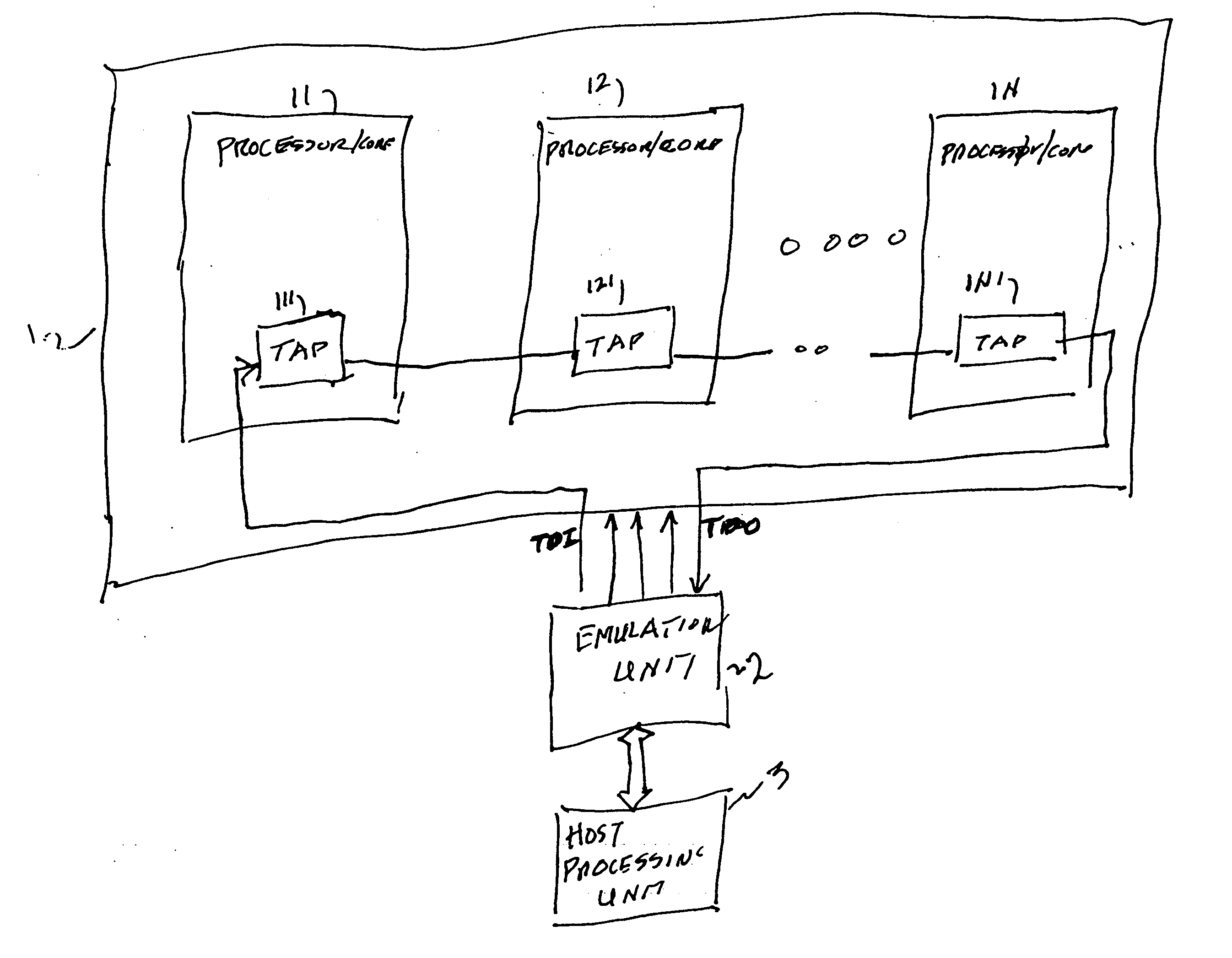
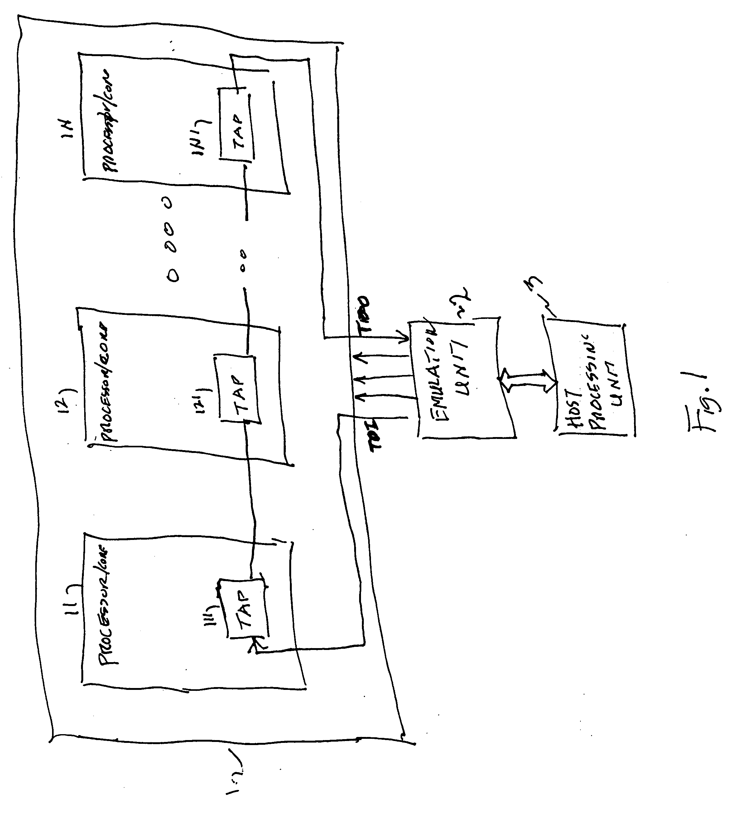
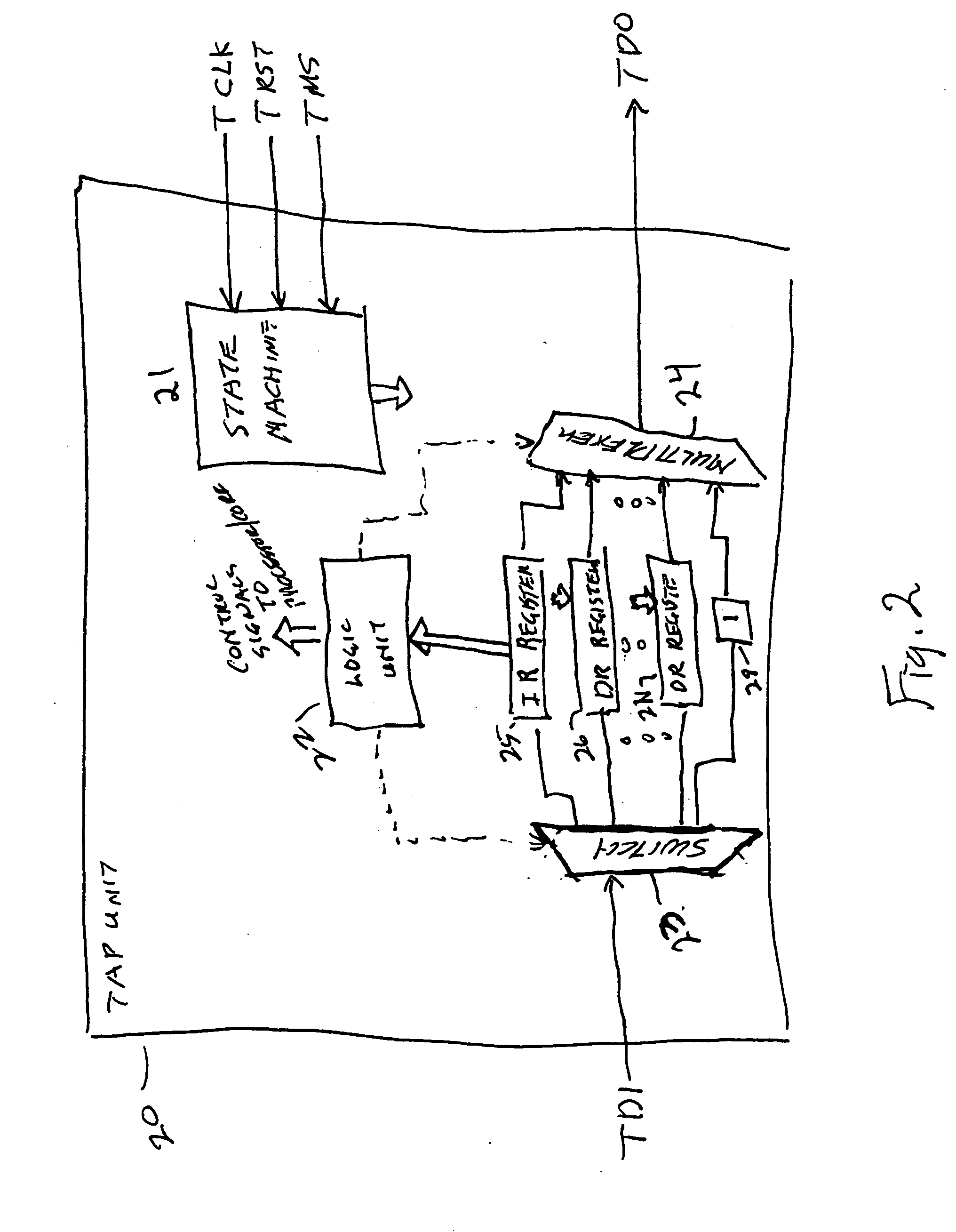
[0029] Referring to FIG. 3, a block diagram of the interface unit 30 mitigating the transfer of data between the plurality of processor / cores 11-1N and the test and debug apparatus is shown. The portion of the current invention that differs from FIG. 1 is designated by numbers beginning with the number three. Coupled to the TAP units 111-11N of each processor / core are switch units 331-33N, respectively. The interface unit 30 includes a TAP unit 301. The TAP unit 301 of the interface unit 30 is coupled to switch unit 39. The switch units 39 and 331-33N are coupled in series. The TDI signal from the test and debug unit, i.e., the emulation unit 2 and the host processing unit 3 of FIG. 1 and FIG. 3, is applied to an input terminal of switch unit 39. The output terminal of switch unit 39 is applied to the input terminal of switch unit 331. The input terminal of each switch unit, except for switch unit 39, is coupled to the output terminal of the p...


PUM


Abstract

An interface unit is provided in a JTAG test and debug procedure involving a plurality of processor cores. The interface unit includes a TAP unit. A switch unit is coupled to the interface unit and switch units are coupled to each of the plurality of processor / cores. When the processor / cores have advanced power management systems, a sleep inhibit signal can be applied to the processor / core state machine preventing the state machine from entering a lower power state. The parameters of the processor / core can be tested to determine when the test and debug procedures can be implemented. When the (power) parameters are to low to permit test and debug, the test and debug unit can provide a command forcing the state machine into a state for which test and debug procedures can be implemented.

Description

[0001] This application is related to provisional U.S. Patent Application Ser. No. 60 / 675,274, (TI-36934PS) filed Apr. 27, 2005, titled “Apparatus and Method to Facilitate Debug and Test in a Multi-Processor System in the Presence of Lower Power and Security Constraints,” for which priority under 35 U.S.C. 119(e)(1) is hereby claimed and which is hereby incorporated herein by reference. RELATED APPLICATIONS [0002] U.S. Patent Application Ser. No. (TI-36934) entitled Apparatus And Method For Coupling A Plurality Of Test Access Ports To External Test And Debug Facility, invented by Robert A. McGowan and filed on even date herewith; and U.S. Patent Application Ser. No. (TI-62360) entitled APPARATUS AND METHOD FOR CONTROLLING POWER, CLOCK, AND RESET DURING TEST AND DEBUG PROCEDDURES FOR A PLURALITY OF PROCESSOR / CORES, invented by Robert A. McGowan and filed on even date herewith are related applications. BACKGROUND OF THE INVENTION [0003] 1. Field of the Invention [0004] This invention ...

Claims


Application Information

Patent Timeline
Patent Type & Authority Applications(United States)
IPC IPC(8): G06F11/00
CPCG06F11/2242
Inventor MCGOWAN, ROBERT A.
Owner TEXAS INSTR INC
Learn More