
Optical data storage and systems utilizing plasmon lenses

a technology of optical data storage and plasmon lens, which is applied in the field of optical recording materials and optical data storage and retrieval systems, can solve the problems of high cost, high cost, and inability to meet the requirements of mass production, and achieve the effects of increasing the optical data storage density, improving recording and/or erasing efficiency, and improving absorption contras

Inactive Publication Date: 2006-11-02
OPTICAL MEMORY STORAGE
View PDF2 Cites 3 Cited by
  • Summary
  • Abstract
  • Description
  • Claims
  • Application Information

AI Technical Summary

Benefits of technology

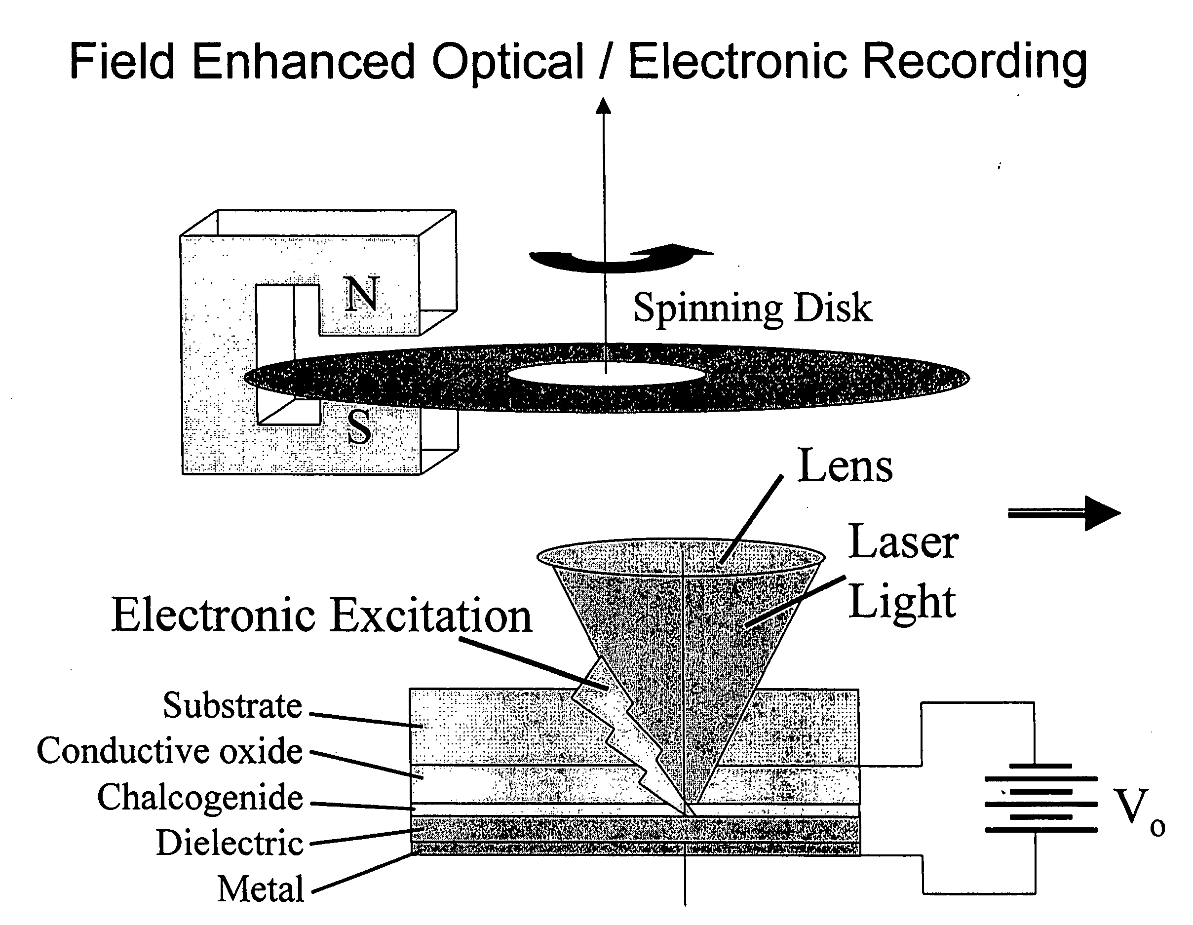
[0017] The instant invention provides an improved optical recording medium and optical data storage system with increased recording and / or erasing efficiencies when using short wavelength or low power excitation sources.
[0018] The optical recording medium of the instant invention is generally a multilayer optical stack that includes a phase change material having a crystalline and amorphous state. In one embodiment, the phase change material shows improved absorption contrast between the crystalline and amorphous states at short wavelengths such as in the blue portion of the visible spectrum. In another embodiment, the optical recording medium includes a crystallizing layer in communication with a phase change material for the purposes of facilitating the crystallization of the phase change material. In another embodiment, the optical recording medium includes means for receiving energy from external fields to provide field enhanced recording.

Problems solved by technology

Subsequent removal of the laser leads to rapid quenching and formation of an amorphous state characterized by structural randomness and disorder.
The currently available optical phase change materials may provide much higher information storage densities than many conventional magnetic memory media, but are currently limited.
Unfortunately, high power blue lasers are not currently economically feasible for use in mass produced products.
In their work, geometric constraints do not allow surface plasmons (SP) on the metallic Sb layer because momentum is not conserved.

Method used


Image

  • Optical data storage and systems utilizing plasmon lenses
  • Optical data storage and systems utilizing plasmon lenses
  • Optical data storage and systems utilizing plasmon lenses

Examples


Embodiment Construction

Blue Lasers

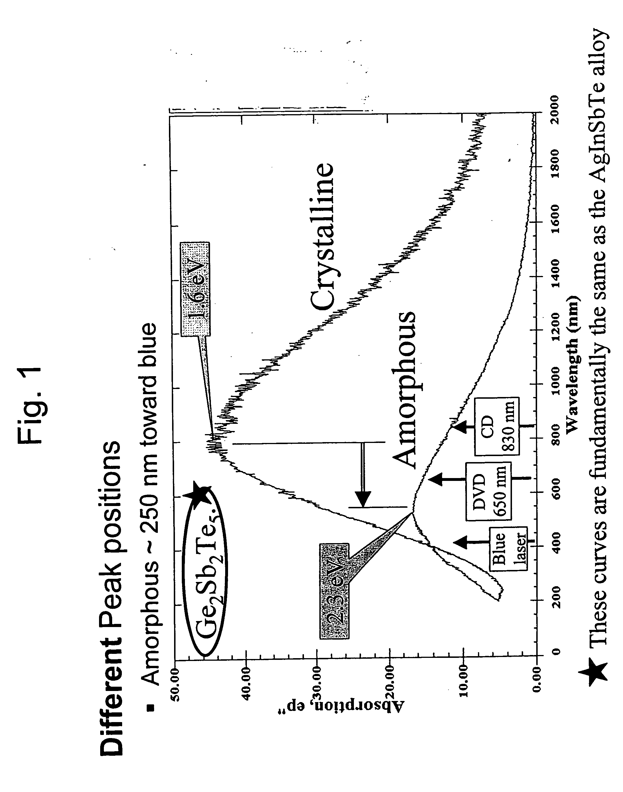
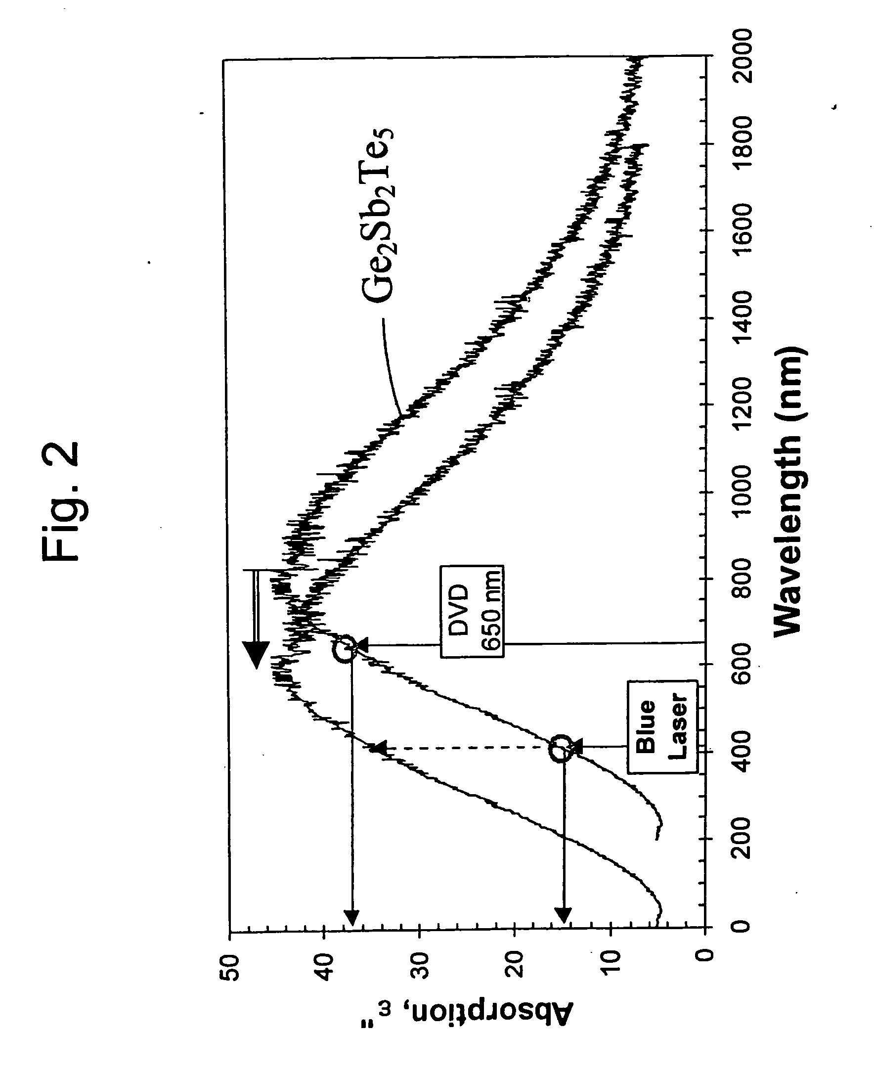
[0029] The present invention provides an optical recording medium and an optical storage and retrieval system suitable for use with blue and other short wavelength laser sources. It confronts two important aspects necessary to realize the benefits of using blue lasers to read, write, and erase information on an optical recording medium. First, the invention addresses the need to develop new phase change materials that are more suitable than current materials for integration into an information storage and retrieval system based on a blue laser. Second, the invention addresses the fact that economical compact blue lasers are expected to have lower powers than the red and near-infrared lasers currently used in optical recording systems.

[0030] A transition to optical storage and retrieval systems based on blue or other short wavelength lasers requires a reconsideration of the suitability of current phase change materials for use as the optical recording medium. One importa...


PUM

PropertyMeasurementUnit
sizeaaaaaaaaaa
sizeaaaaaaaaaa
sizeaaaaaaaaaa

Abstract

A light-plasmon coupling lens including an optically transparent substrate having a light incident surface and a light-plasmon coupling surface opposite the light incident surface. The light-plasmon coupling surface including at least a set of circular concentric peaks / valleys which form a Fourier sinusoidal pattern in the radial direction of the circular concentric peaks / valleys. A conformal layer of metal is deposited on the light-plasmon coupling surface of the substrate and has aperture at the center of thereof through which plasmons are transmitted. An optical recording medium including a light-plasmon coupling lens.

Description

CROSS-REFERENCE TO RELATED APPLICATIONS [0001] The present invention relates, and is entitled to the benefit of the earlier filing date and priority of U.S. Provisional Patent Application-No. 60 / 316,566 having a filing date of Sep. 1, 2001, the disclosure of which is hereby incorporated by reference; and is a divisional of U.S. patent application Ser. No. 10 / 232,355, filed on Aug. 30, 2002, the disclosure of which is hereby incorporated by reference.FIELD OF THE INVENTION [0002] The present invention pertains to optical recording materials and optical data storage and retrieval systems. More specifically, the instant invention provides an optical recording medium comprising a phase change material that may be efficiently recorded and erased using a short wavelength laser. Most specifically, the instant invention includes a provision within an optical stack for supplying supplemental energy to a phase change material to enable recording and erasing via a low power energy source. Also...

Claims


Application Information

Patent Timeline
Patent Type & Authority Applications(United States)
IPC IPC(8): G11B7/135G11B5/58G11B7/00G11B7/004G11B7/0045G11B7/0055G11B7/006G11B7/09G11B7/095G11B7/125G11B7/243G11B7/251G11B7/257G11B11/03G11B11/105G11B11/11G11B11/115G11B11/12G11B15/04G11B19/04G11B20/18G11B27/36
CPCB82Y10/00G11B2007/24316G11B7/00557G11B7/006G11B7/1275G11B7/1374G11B7/1387G11B7/24065G11B7/243G11B7/2433G11B7/251G11B7/252G11B7/2531G11B7/2534G11B7/257G11B7/2585G11B7/259G11B2007/24308G11B2007/2431G11B2007/24312G11B2007/24314G11B7/00454
Inventor OVSHINSKY, STANFORD R.STRAND, DAVIDTSU, DAVID
Owner OPTICAL MEMORY STORAGE
Learn More