
Latching structure for cover and transfer tool

a technology of latching structure and transfer tool, which is applied in the direction of lid/cover non-removal, transportation and packaging, packaging, etc., can solve the problems of increasing the manufacturing cost of the transfer tool itself, and achieve the effect of reducing manufacturing costs, flexible design for arranging the cover and the supporting body, and improving the design

Inactive Publication Date: 2006-11-02
KOKUYO S&T CO LTD
View PDF21 Cites 12 Cited by
  • Summary
  • Abstract
  • Description
  • Claims
  • Application Information

AI Technical Summary

Benefits of technology

[0010] With such configuration, by providing the latching means at the rotating shaft itself at which the supporting body at least contacts the cover in order to rotatably attach both, or proximate thereof, it will be possible to effectively avoid the necessity of providing a particular means for maintaining the position of the cover at different spots of the cover and the supporting body. With such configuration, specifications for the supporting body and the cover other than that of the location of the rotating shaft will not be limited, and the flexibility of design for arranging the cover and the supporting body can be suitably improved.
[0015] For suitably latching the cover, the supporting body and the cover shall be made of resin so that bending, which is a characteristic of resin materials, can be effectively utilized for suitably latching the supporting body and the cover, and also easily unlatching the same from the latched condition.
[0017] According to the present invention, by providing the latching means at the rotating shaft itself at which the supporting body at least contacts the cover in order to rotatably attach both, or proximate thereof, it will be possible to effectively avoid the necessity of providing a particular means for maintaining the position of the cover at different spots of the cover and the supporting body. With such configuration, specifications for the supporting body and the cover other than that of the location of the rotating shaft will not be limited and the flexibility of design for arranging the cover and the supporting body can be suitably improved, and the structure of the supporting body and the cover can be simplified so as to achieve reductions in manufacturing costs.
[0018] Particularly, when employing the cover latching structure according to the present invention to a transfer tool, it is possible to provide a transfer tool that certainly latches the cover and that is of reduced manufacturing costs.

Problems solved by technology

Accordingly, the structure of the transfer tool main body or the cover will become complicated which consequently results in increased manufacturing costs of the transfer tool itself.
Such problems are not limited to transfer tools only but similar problems may arise in structures in which a cover is attached to a supporting body in a rotating manner.

Method used


Image

  • Latching structure for cover and transfer tool
  • Latching structure for cover and transfer tool
  • Latching structure for cover and transfer tool

Examples


Embodiment Construction

[0028] An embodiment of the present invention will now be explained while referring to the drawings.

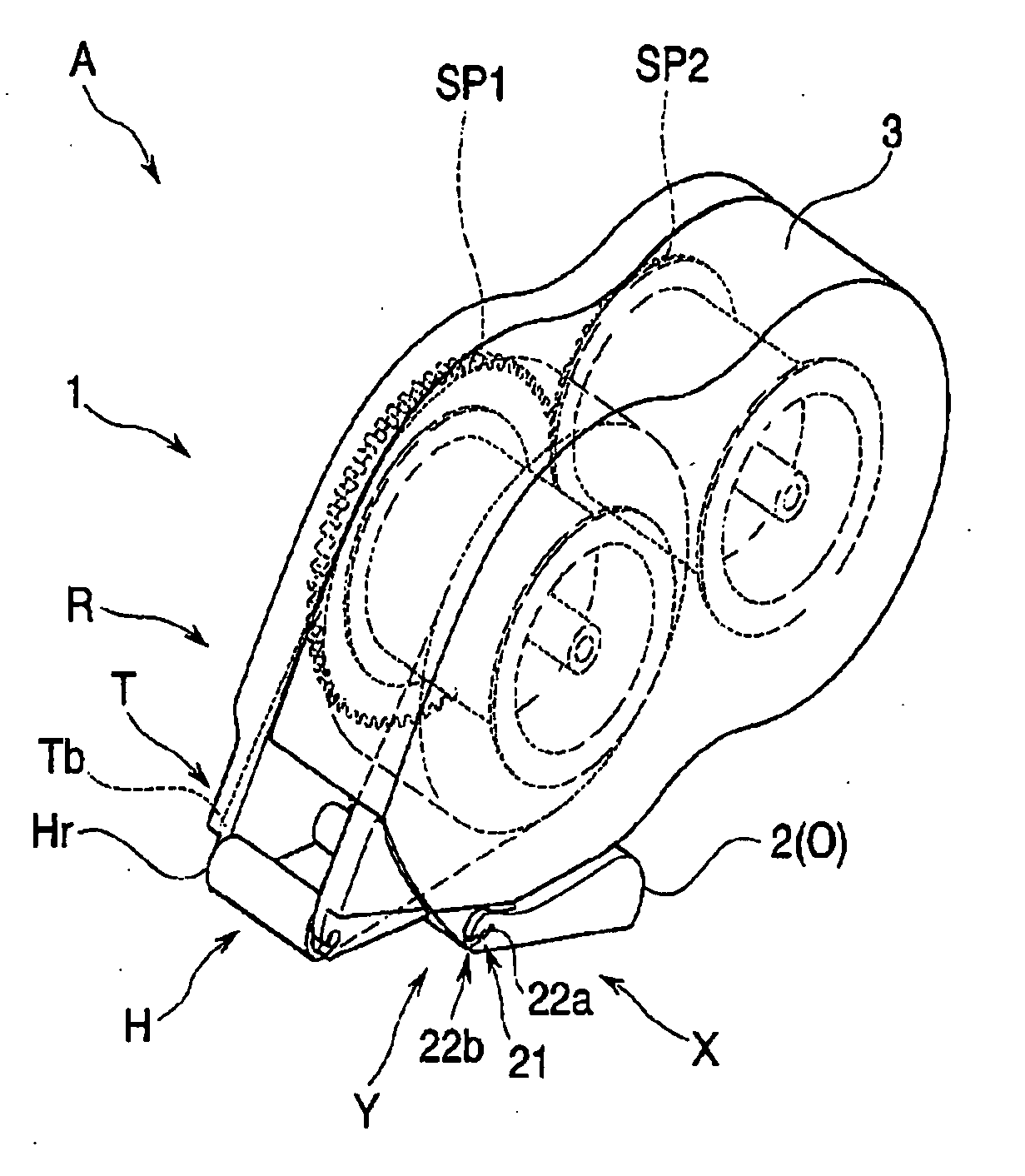
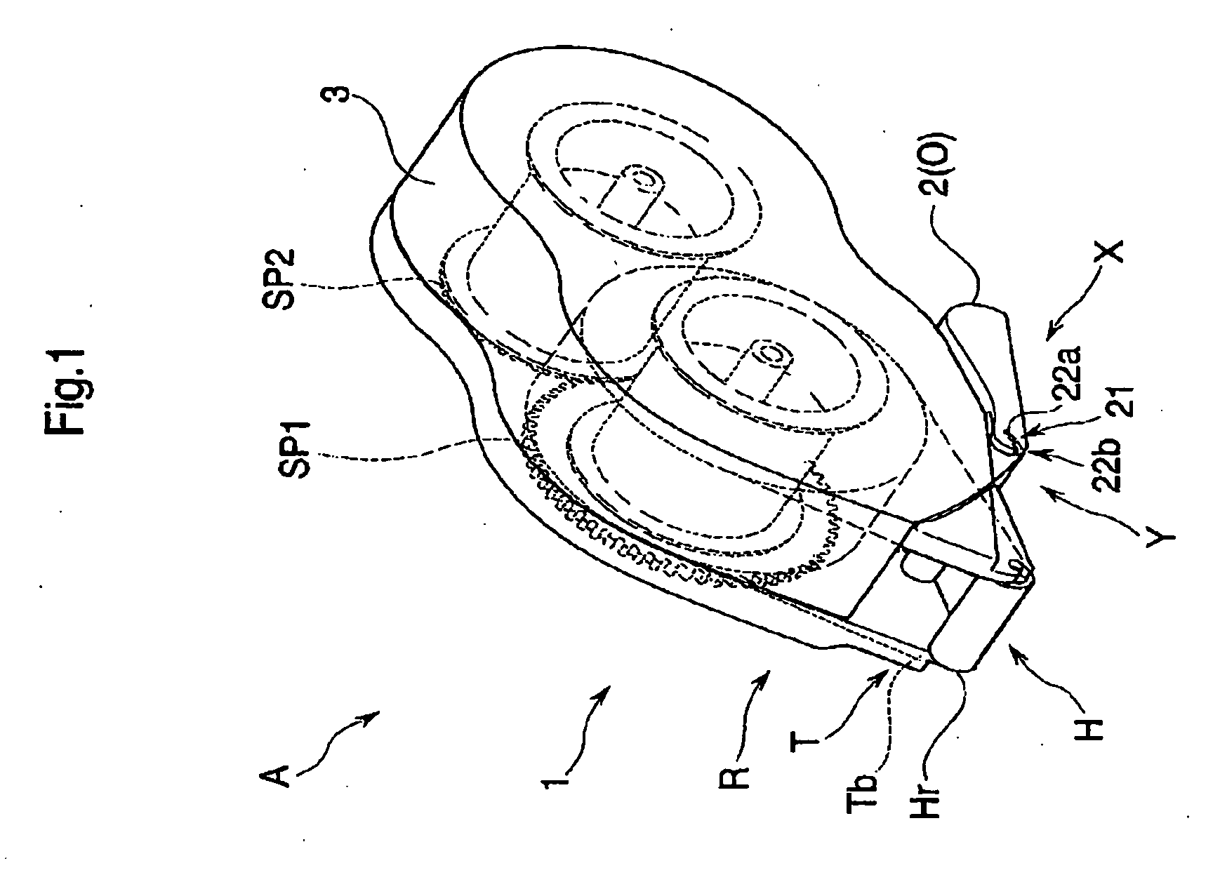
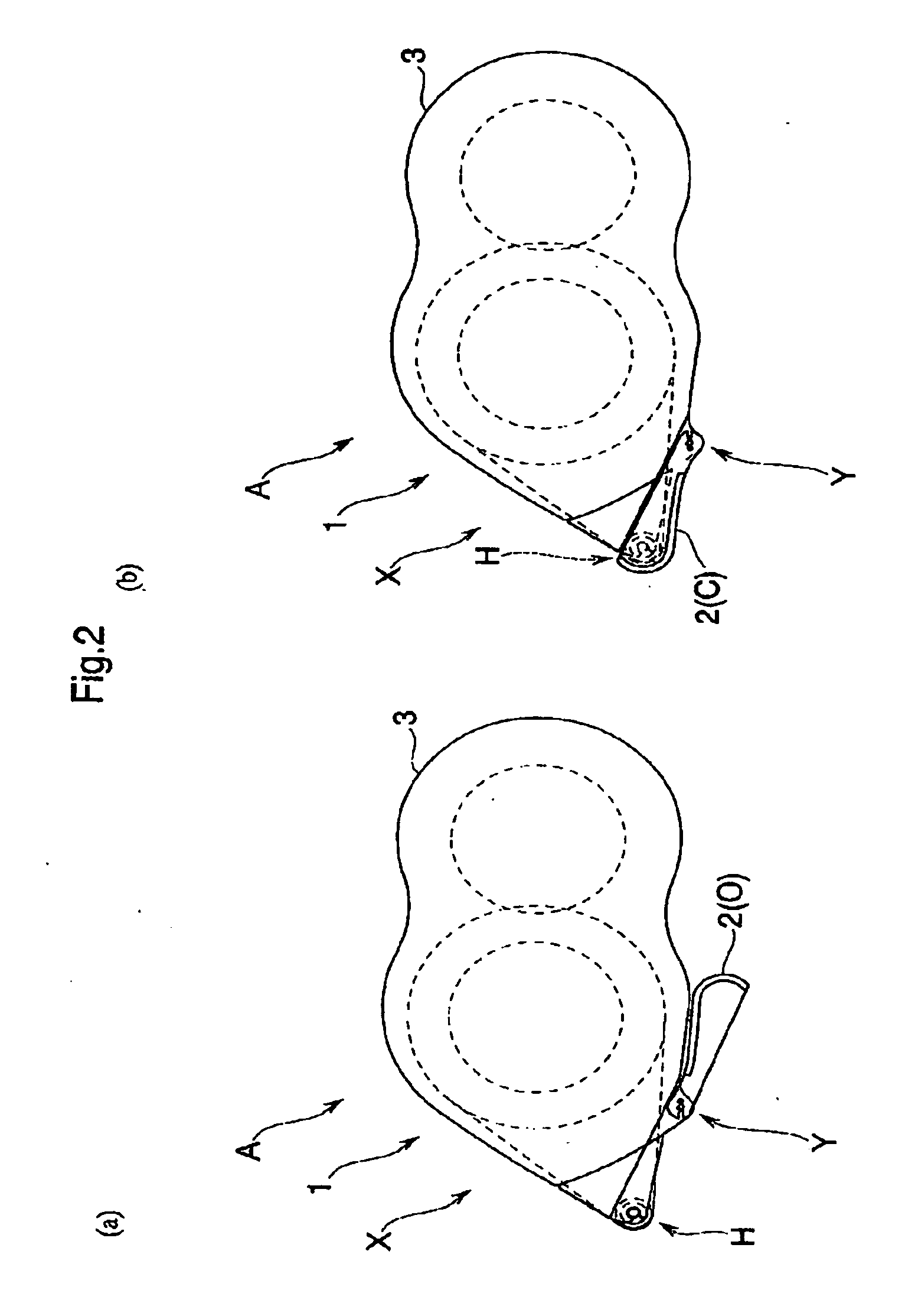
[0029] A transfer tool A employing the latching structure X comprising the cover latching structure according to the present embodiment is shown in FIGS. 1 to 4.

[0030] The transfer tool A is mainly comprised of a transfer tool main body 1 corresponding a supporting body and a cover 2 attached to the transfer tool main body 1 in a rotating manner.

[0031] Here, the transfer tool A employing the mounting structure X of the cover 2 according to the present embodiment includes the transfer tool main body 1 and the cover 2 attached to the transfer tool main body 1 in a rotating manner and employs the cover latching structure X for latching the cover 2 with respect to a predetermined position, and is arranged in that latching means Y for latching the cover 2 with respect to the transfer tool main body 1 is provided proximate of a rotating shaft 21 to be explained later around which the cov...


PUM


Abstract

It is an object to provide an latching structure of simplified structure but capable of certainly latching a cover. The invention is an latching structure X and a transfer tool A employing the latching structure X for the cover 2 including a transfer tool main body 1 and a cover 2 attached to a case 3 of the transfer tool main body 1 in a rotating manner for latching the cover at a predetermined position, and a transfer tool A employing the latching structure X, wherein an latching means Y for latching the cover with respect to the case 3 is provided proximate of a rotating shaft 21 around which the cover 2 rotates.

Description

BACKGROUND OF THE INVENTION [0001] 1. Field of the Invention [0002] The present invention relates to a latching structure for latching a cover attached to a supporting body at a predetermined position. [0003] 2. Description of the Related Art [0004] There have conventionally been suggested structures for latching cover attached to supporting body in a rotating manner at predetermined positions. [0005] For instance, taking a transfer tool as an example, there is disclosed a case as in Japanese Patent Laid-Open Publication No. 2003-54190 in which a cover is supported in a rotating manner between an open position in which a transfer head is exposed when the transfer tool is in use and a closed position in which the transfer head is covered when the transfer tool is not in use. [0006] However, it is necessary to provide a protrusion at a position of the transfer tool main body proximate of the transfer head in order to latch the cover at the predetermined position or to provide another ...

Claims


Application Information

Patent Timeline
IPC IPC(8): H01H9/02
CPCB65H37/007
Inventor KINUGASA, SHUJIMATSUSHITA, KINYASHIMA, HIDETO
Owner KOKUYO S&T CO LTD
Learn More