
Cordless blind structure

Inactive Publication Date: 2006-11-02
CHING FENG BLINDS INC CO LTD
View PDF7 Cites 10 Cited by
  • Summary
  • Abstract
  • Description
  • Claims
  • Application Information

AI Technical Summary

Benefits of technology

[0003] It is, therefore, the primary purpose of the present invention to provide a cordless blind structure, including a blind, a plurality of control seats, and a plurality of guide tracks wherein the blind has a blind body fixedly attached to the underside of a headrail, and the control seats along with guide blocks of connecting elements equidistantly attached at both lateral side edge of the blind body are cooperatively operated with the guide tracks thereof, permitting a retaining block protruding at one side of a switch element of each control seat to slide up or down at a guide groove of each guide track therein and abut against therewith for location so as to stably collect or expand the blind body in a convenient and speedy manner without the use of any lift cords, efficiently achieving safer application thereby.
[0004] It is, therefore, the second purpose of the present invention to provide a cordless blind structure wherein the switch element of each control seat is equipped with a switching portion capable of being bent upwards or downwards to actuate the retaining block switched into a vertical or a horizontal position at the guide groove of the guide track therein for the effects of sliding upwards / downwards movement therein or abutting location thereby respectively, achieving more convenient and flexible application thereof.

Problems solved by technology

The conventional blind structure usually found on the market is made up of a roller gear set reciprocally operated with a lift cord set and a tape ladder set, which are tediously assembled in a rather time-consuming and painful manner.
And, children playing around can easily get caught in the dangling lift cord that, if the children are not released immediately there-from or when the lift cord is unlocked to withdraw upwards, can accidentally strangle and hurt the children caught therein.
Thus, the conventional blind is quite unsafe in application thereof.

Method used


Image

  • Cordless blind structure
  • Cordless blind structure
  • Cordless blind structure

Examples


Embodiment Construction

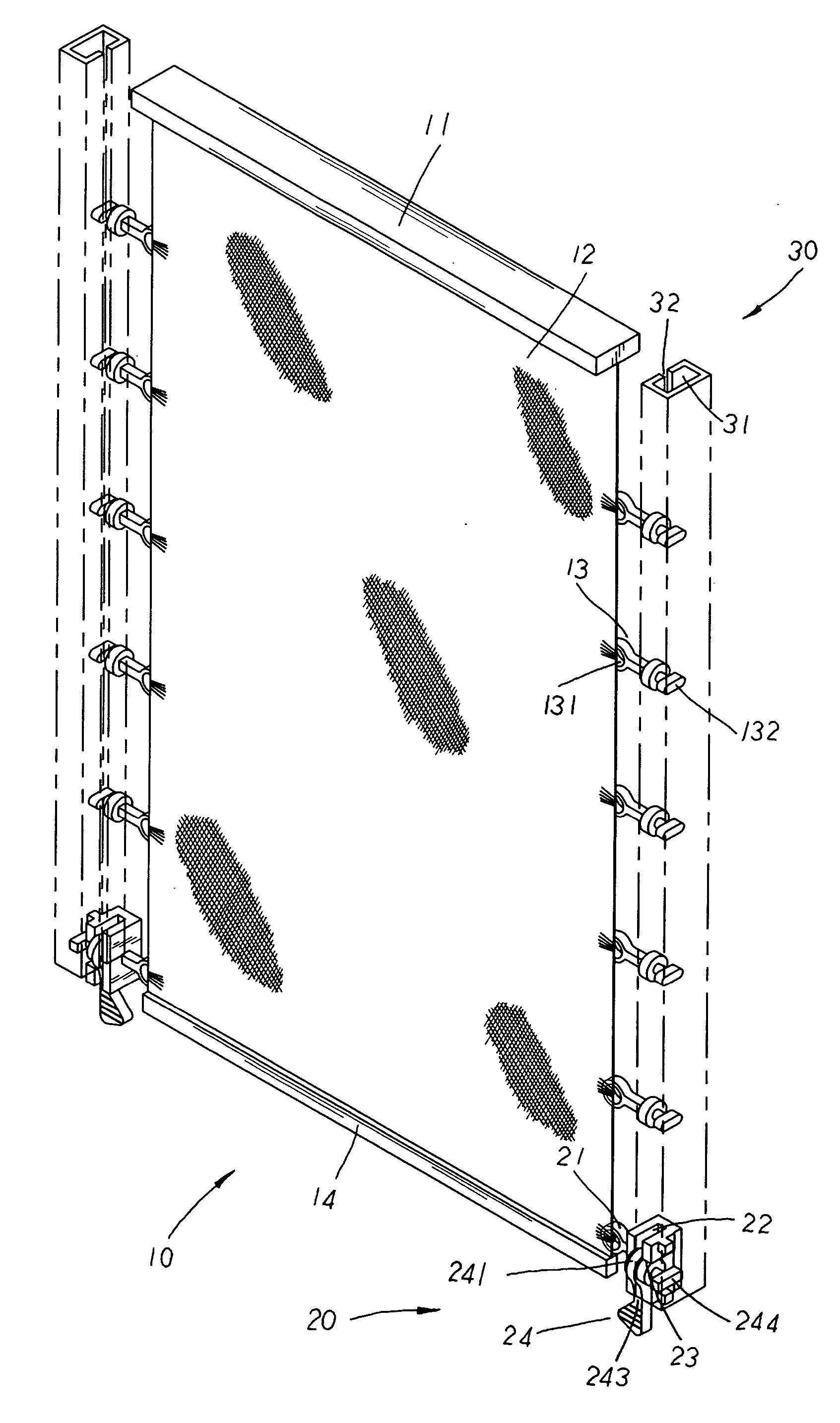
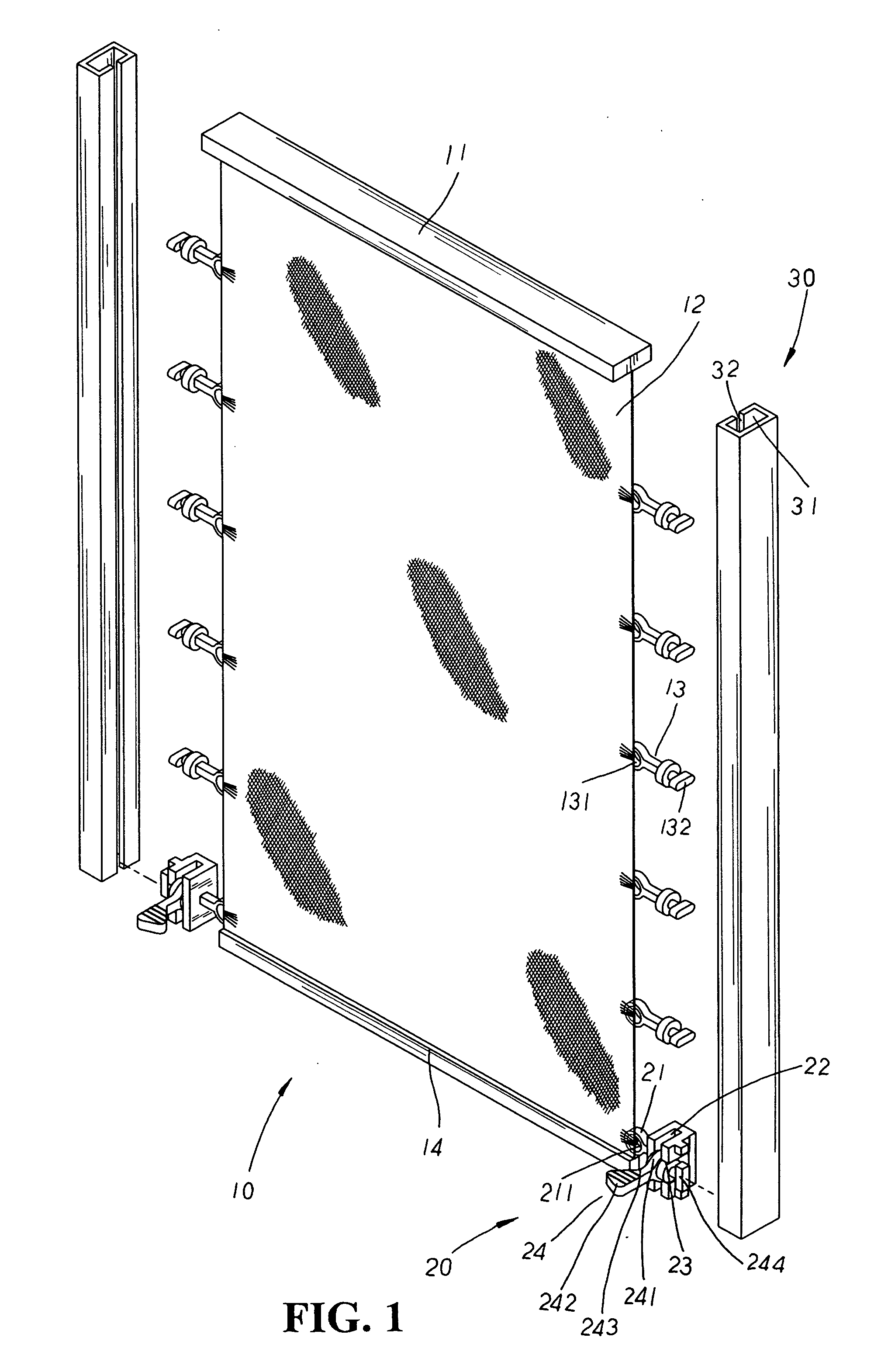
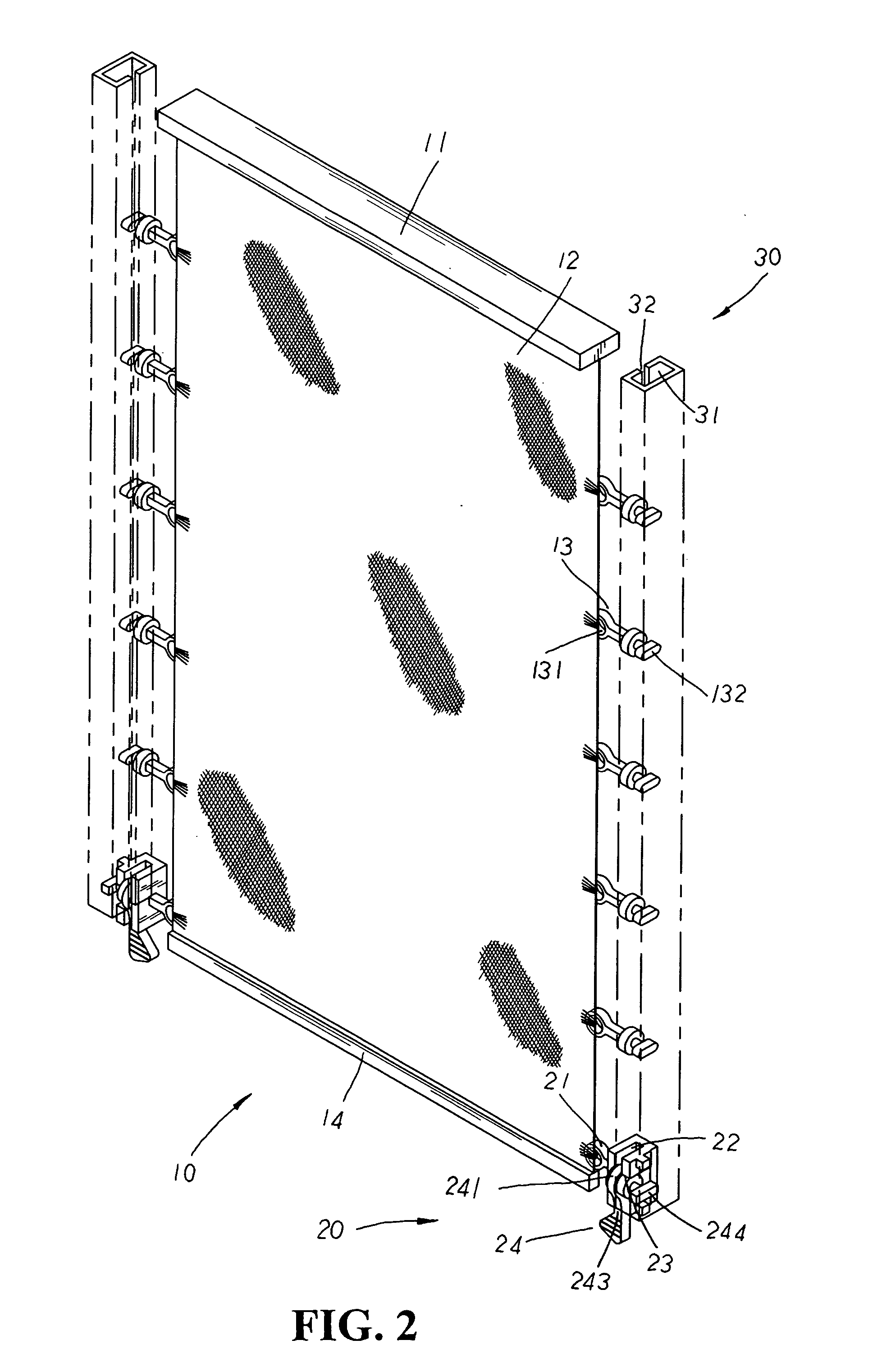
[0013] Please refer to FIG. 1 showing an exploded perspective view of the present invention. The present invention is related to a cordless blind structure, comprising a blind 10, a plurality of control seats 20, and a plurality of guide tracks 30. The blind 10 is made up of a blind body 12 fixedly attached to the underside of a headrail 11, and a plurality of connecting elements 13 that, each having a connecting hole 131 disposed at one side thereon and a guide block 132 protruding at the other side thereof, are equidistantly attached (preferably via sewing) to both lateral side edges of the blind body 12 thereon. The blind body 12 also has a holding weight portion 14 attached at the bottom edge thereon. The control seats 20 (referring also to FIG. 4) each having an engaging element 21 with an engaging hole 211 disposed thereon are symmetrically fixed (preferably via sewing) at both bottom lateral edges right above the holding weight portion 14 of the blind body 12 thereon. Inside ...


PUM


Abstract

A cordless blind structure comprises a blind, and a plurality of control seats and guide tracks wherein the blind has a blind body fixedly attached to the underside of a headrail, a plurality of connecting elements, each having a guide block to be adapted to a guide groove of each guide track, fixed to both lateral side edges of the blind body, and a holding weight portion attached at the bottom edge thereof. The control seat, fixed above the holding weight portion thereon, has a set of crisscrossed positioning groove and pivoting groove appropriately defining therein for the accommodation of a switch element having a transverse T-shaped retaining block to be mounted into the guide groove of each guide track for sliding movement or abutting location therein, permitting the blind body to be stably collected or easily expanded without the use of any lift cords for achieving safer application thereby.

Description

BACKGROUND OF THE INVENTION [0001] The present invention is related to a cordless blind structure, including a blind, and a plurality of control seats and guide tracks wherein the blind has a blind body fixedly attached to the underside of a headrail, a plurality of connecting elements each having a guide block equidistantly attached to both lateral side edges of the blind body, a holding weight portion attached at the bottom edge thereon, and the control seats symmetrically fixed at the bottom lateral edges above the holding weight portion; whereby, the control seats along with the connecting elements are cooperatively operated with the guide tracks thereof to stably collect or expand the blind body in a convenient and speedy manner without the use of any lift cords, efficiently achieving safer application thereby. [0002] The conventional blind structure usually found on the market is made up of a roller gear set reciprocally operated with a lift cord set and a tape ladder set, whi...

Claims


Application Information

Patent Timeline
IPC IPC(8): E06B9/06A47H5/14E06B9/24E06B9/262E06B9/32
CPCE06B9/262E06B2009/2627E06B2009/2622E06B9/32
Inventor LIANG, WEN YING
Owner CHING FENG BLINDS INC CO LTD
Learn More