Retractable lifting blades for aircraft
- Summary
- Abstract
- Description
- Claims
- Application Information
AI Technical Summary
Benefits of technology
Problems solved by technology
Method used
Image
Examples
Embodiment Construction
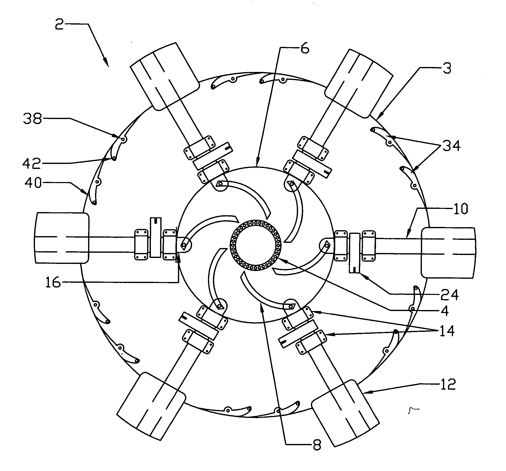
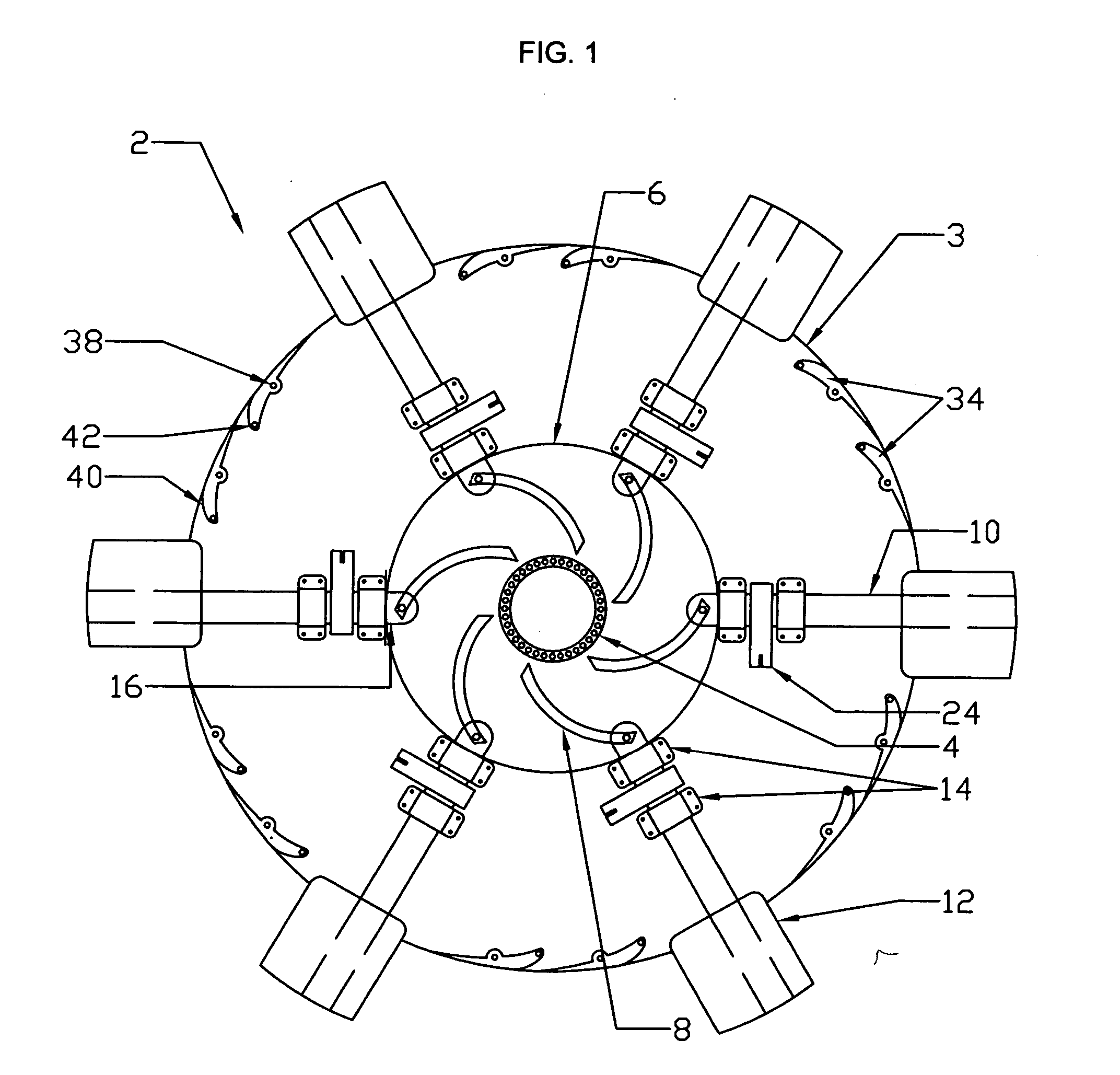
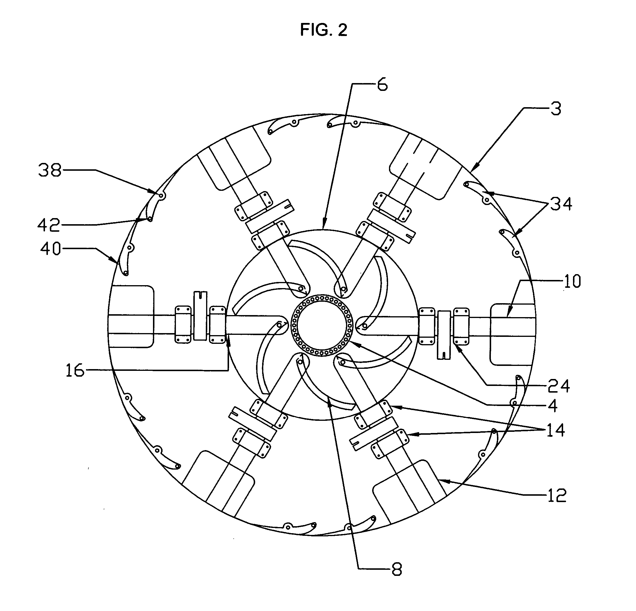
[0046] A rotor head assembly 2 of the preferred embodiment is depicted in FIG. 1. The figure is not to scale. FIG. 1 depicts the condition of a helicopter in flight with the blades fully extended. This figure is a view from the top of the helicopter. The basic components are as follows. At the center of the drawing is depicted the hollow mast 4, which in the preferred embodiment is a standard helicopter mast. The drive shaft (not shown) is within the mast. Around the mast 4 are the rotor head bearings (not shown in this view) supporting the rotor head assembly 2. In turn, the operating cam 6 is bearing mounted (not shown in this view) on the rotor head 3 and can be rotated relative to the mast 4 and the rotor head assembly 2. Cam grooves 8 are shown, in which are mounted the proximal ends of the blade spars 10. The drawing shows one means of deploying the blades 12, utilizing cam grooves 8 having one particular configuration, but the grooves may be longer or shorter, have a deeper o...
PUM
 Abstract
Description
Claims
Application Information
 - R&D
- Intellectual Property
- Life Sciences
- Materials
- Tech Scout
- Unparalleled Data Quality
- Higher Quality Content
- 60% Fewer Hallucinations
Browse by: Latest US Patents, China's latest patents, Technical Efficacy Thesaurus, Application Domain, Technology Topic, Popular Technical Reports.
© 2025 PatSnap. All rights reserved.Legal|Privacy policy|Modern Slavery Act Transparency Statement|Sitemap|About US| Contact US: help@patsnap.com


