
Robot cleaner driving method

a technology for cleaning robots and cleaning machines, applied in the direction of vehicle position/course/altitude control, process and machine control, instruments, etc., can solve the problems of unchanged driving method of zigzag-type robot cleaners, unnecessarily repeating and difficult to confirm the cleaning operation of robot cleaners. complete, improve the cleaning efficiency of the entire cleaning space, and easily confirm the cleaning operation progress

Inactive Publication Date: 2006-10-26
LG ELECTRONICS INC
View PDF2 Cites 19 Cited by
  • Summary
  • Abstract
  • Description
  • Claims
  • Application Information

AI Technical Summary

Benefits of technology

[0011] Therefore, the present invention has been made in view of the above problems, and it is an object of the present invention to provide a robot cleaner driving method that is capable of partitioning a space to be cleaned into one or more cells, which are small spaces, setting the cleaning order, in which the cleaning space is cleaned, on a per cell basis, and driving the robot cleaner such that the cleaning operation of the robot cleaner is performed, thereby the cleaning efficiency of the robot cleaner irrespective of an obstruction, reducing unnecessary driving operation of the robot cleaner, and predicting completion of the cleaning operation of the robot cleaner.

Problems solved by technology

As a result, the driving operation of the robot cleaner is unnecessarily repeated.
Furthermore, the zigzag-type robot cleaner driving method is not changed according to the progress of the cleaning operation.
Consequently, it is difficult to confirm when the cleaning operation of the robot cleaner is completed.
Consequently, the cleaning space is incompletely cleaned, and therefore, the cleaning efficiency of the robot cleaner is decreased.

Method used


Image

  • Robot cleaner driving method
  • Robot cleaner driving method
  • Robot cleaner driving method

Examples


Embodiment Construction

[0053] Now, preferred embodiments of the present invention will be described in detail with reference to the accompanying drawings.

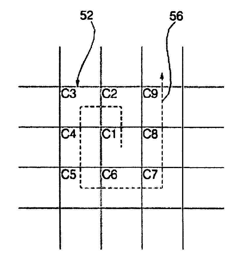
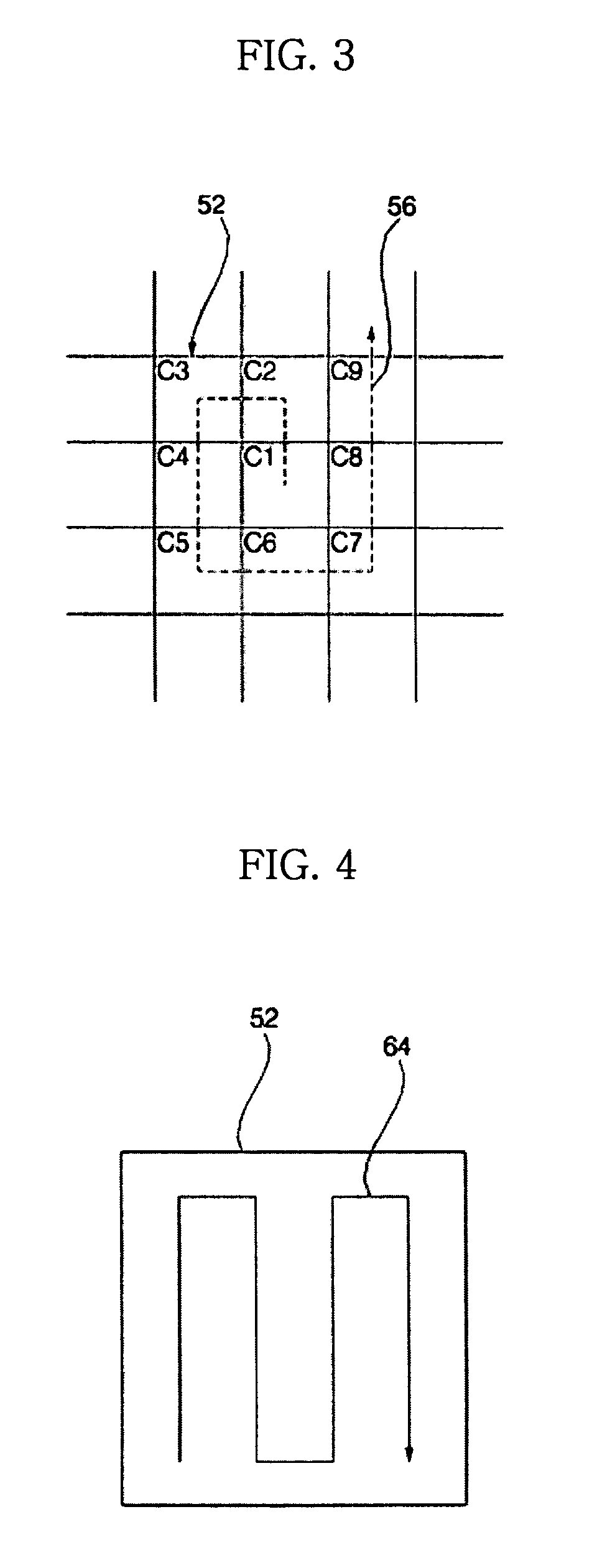
[0054] FIGS. 3 to 8 illustrate a robot cleaner driving method according to a first preferred embodiment of the present invention, wherein FIG. 3 is a view illustrating implementation of the robot cleaner driving method according to the first preferred embodiment of the present invention, FIG. 4 is a view illustrating a drive route at a first cleaning step, FIG. 5 is a view illustrating a drive route at a second cleaning step, FIG. 6 is a view illustrating a drive route at a third cleaning step, FIG. 7 is a view illustrating a drive route at a fourth cleaning step, and FIG. 8 is a view illustrating a drive route at a fifth cleaning step.

[0055] As illustrated in FIG. 3, the robot cleaner driving method according to the first preferred embodiment of the present invention comprises: one or more setting steps of setting an imaginary space, including a space...


PUM


Abstract

Disclosed herein is a robot cleaner driving method. The robot cleaner driving method comprises one or more setting steps of setting an imaginary space, including a space to be cleaned, and partitioning the imaginary space into one or more cells, one or more cleaning steps, which are assigned to the respective cells, of driving the robot cleaner to clean the assigned cells such that the directions of driving the robot cleaner are perpendicular to each other in some of the assigned cells, and one or more turning steps, which are performed after the respective cleaning steps or the respective setting steps are completed, of driving the robot cleaner to the next cell to be cleaned, at which one of the cleaning steps assigned to the cell is performed, such that the imaginary space is cleaned in the direction of a spiral on a per cell basis. According to the present invention, unnecessary driving operations of the robot cleaner are reduced, completion of the cleaning operation is predicted, and the cleaning efficiency of the robot cleaner is improved.

Description

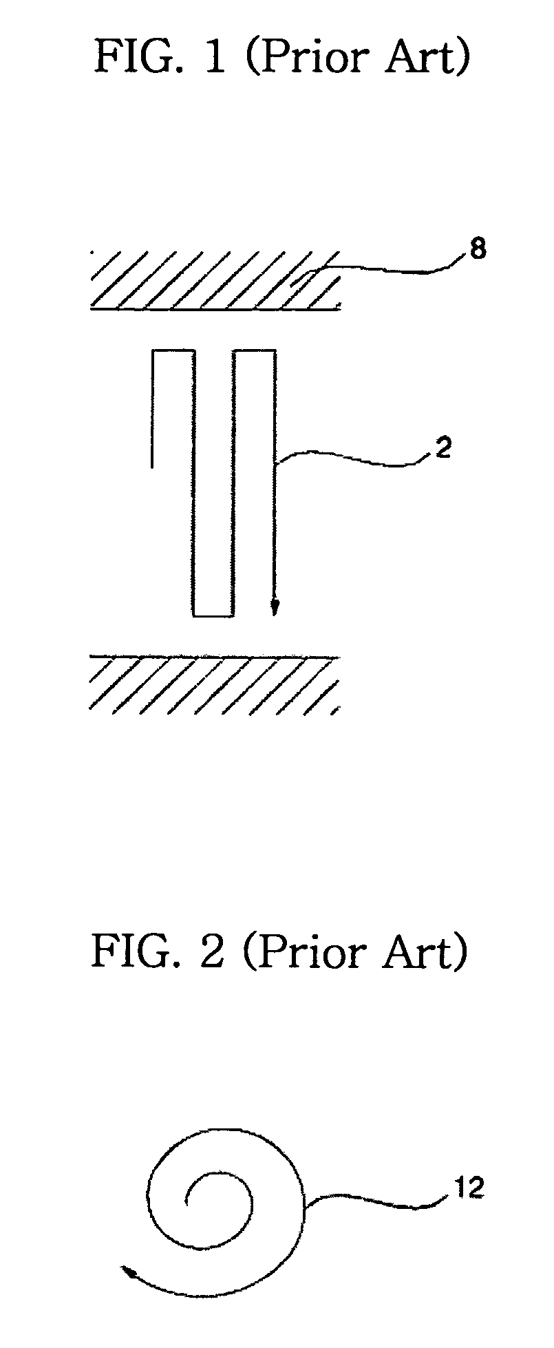
BACKGROUND OF THE INVENTION [0001] 1. Field of the Invention [0002] The present invention relates to a robot cleaner driving method, and, more particularly, to a robot cleaner driving method that is capable of partitioning a space to be cleaned into one or more cells, setting drive routes along which the robot cleaner is driven in the respective partitioned cells, and cleaning the respective partitioned cells in order. [0003] 2. Description of the Related Art [0004] Generally, a robot cleaner is a cleaning apparatus incorporating a microcomputer, in which a robot cleaner driving method is implemented. A driving unit of the robot cleaner is controlled by the microcomputer such that the robot cleaner performs a cleaning operation for cleaning a space to be cleaned while the robot cleaner is driven. [0005] Conventional robot cleaner driving methods are classified into a zigzag-type robot cleaner driving method and a spiral-type robot cleaner driving method. [0006]FIGS. 1 and 2 illustra...

Claims


Application Information

Patent Timeline
Patent Type & Authority Applications(United States)
IPC IPC(8): B08B7/04B08B5/04
CPCG05D2201/0203G05D1/0219E04G17/0657E04G17/0707
Inventor KIM, JONG SUNG
Owner LG ELECTRONICS INC
Learn More